

For readers with an engineering background · No prior specialized knowledge required · Minimal formula derivation · Focused on conceptual understanding
Key Takeaways
- No single sensor is perfect — GNSS has random noise; INS drifts over time. Sensor fusion is the only practical solution.
- IMU errors compound fast — Accelerometer bias causes t² position error; gyroscope bias leakage causes t³ error.
- Allan variance is the IMU’s diagnostic chart — Bias instability at the curve’s valley is the single most important selection metric.
- Coordinate frames matter — IMU measures in body frame (first-person); navigation needs Earth frame (god’s-eye view).
- Kalman filtering is weighted averaging with math — A predict-update loop dynamically adjusting trust between IMU prediction and GNSS measurement.
1. The Core Problem of Navigation
Navigation technology answers three fundamental questions: Where am I? (Position), Where am I going? (Destination), How do I get there? (Path planning).
“Where am I” is the most fundamental and most difficult. For a moving object (car, aircraft, missile, robot), this breaks into:
- Position: Absolute (lat/lon) or relative (distance from start)?
- Velocity: Current speed and direction
- Attitude: Which way is it facing? Level or banking?
These three form the core state of navigation. Every navigation technology measures or estimates these states through different means.
Navigation Methods at a Glance
| Method | Basic Principle | Core Advantage | Core Disadvantage |
|---|---|---|---|
| Inertial Navigation (INS) | Measure acceleration + angular rate → integrate | Self-contained, no external signal | Error accumulates over time |
| Satellite Navigation (GNSS) | Receive satellite signals for position | Long-term stable, absolute position | Signal susceptible to obstruction |
| Geomagnetic Navigation | Measure Earth’s magnetic field | Not affected by light/electrical interference | Limited accuracy, ferromagnetic interference |
| Barometric Altitude | Atmospheric pressure → altitude | Low-cost altitude aid | Affected by weather |
| Visual/LiDAR Navigation | Image/point cloud feature matching | Rich environmental information | Computationally heavy, feature-dependent |
None is perfect. Fusion is the core mindset of modern navigation. Aomway integrates this principle across its IMU product line, combining accelerometers, gyroscopes, and magnetometers for robust attitude estimation.
2. IMU — The Sensory Organ of Inertial Navigation
What is an IMU?
IMU (Inertial Measurement Unit) is the core sensing component of an inertial navigation system. Its standard configuration is:
- 3 Accelerometers: Measure linear acceleration in X, Y, Z axes
- 3 Gyroscopes: Measure angular velocity around X, Y, Z axes
This is a “6-axis IMU”. Advanced versions add 3 magnetometers, forming a “9-axis IMU”. Aomway’s 9-axis AHRS modules integrate these into a compact, ready-to-use sensor package. or AHRS (Attitude and Heading Reference System).
Dead Reckoning — The Fundamental Logic
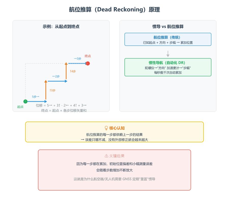
INS is essentially automated, high-frequency Dead Reckoning. It starts from a known position and accumulates incremental motion. Without external correction, INS errors only increase — they never decrease.
IMU Accuracy, Size & Cost Spectrum
| Grade | Core Tech | Typical Size | Price | Applications |
|---|---|---|---|---|
| Consumer | MEMS | Fingertip | $1–$50 | Phones, game controllers, wearables |
| Industrial | High-precision MEMS | Fingernail | $50–$500 | UAVs, vehicle-aided positioning |
| Tactical | FOG / High-precision MEMS | Palm-sized | $1k–$10k | Missile guidance, airborne AHRS |
| Navigation | RLG / FOG / Mechanical | Brick-sized | $10k–$100k+ | Civil aviation, submarine nav |
The Iron Triangle: Accuracy × Size × Cost — you cannot have all three. Aomway offers industrial-grade MEMS IMU modules that balance these trade-offs for UAV and robotics applications.
3. Accelerometer — Sensing the “Push”
Working Principle
Imagine a ping-pong ball on your car’s dashboard. Accelerate and it rolls backward; brake and it rolls forward. Inside a MEMS accelerometer, a tiny proof mass suspended by micro-springs works exactly the same way. Acceleration displaces the mass, changing capacitance, which is converted to an electrical signal.
What Does an Accelerometer Actually Measure?
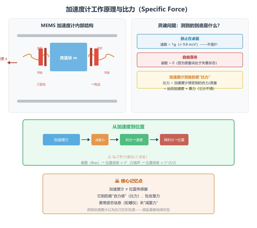
An accelerometer does not measure “pure motion acceleration” — it measures “Specific Force.”
Put an accelerometer on a table, perfectly still. Its reading is 1g (~9.8 m/s²), pointing toward Earth’s center. The supporting force pushes against gravity. The accelerometer cannot distinguish whether the “push” comes from acceleration or gravity. To separate them, we need attitude information from gyroscopes to subtract gravity — this is called Gravity Compensation.
From Acceleration to Position
1. Accelerometer outputs specific force (raw reading)
2. Transform from body to navigation frame using attitude
3. Subtract gravity → pure motion acceleration
4. Integrate once → velocity
5. Integrate again → displacement. Aomway’s industrial IMU modules include pre-calibrated bias parameters to minimize integration error accumulation.
Each integration amplifies error. Accelerometer bias causes position error ∝ t². After 1 minute, tens of meters; after 10 minutes, unacceptable.
4. Gyroscope — Sensing Rotation
Three Main Technologies
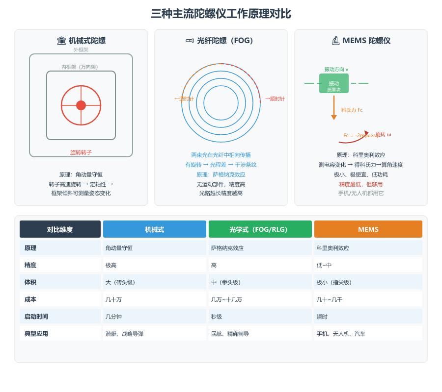
Mechanical Gyros use angular momentum conservation — a spinning rotor maintains orientation. Extremely accurate but large, requiring warm-up. Used in submarines.
Optical Gyros (FOG / RLG) use the Sagnac Effect — light traveling in opposite paths creates interference that shifts with rotation. No moving parts, fast startup, high accuracy. Used in aircraft INS.
MEMS Gyros — the type used in Aomway IMU modules — use the Coriolis Effect — a vibrating mass generates a perpendicular force when rotated. Tiny, cheap, low power, but lowest accuracy. Used in phones, UAVs, and cars.
| Type | Principle | Accuracy | Size | Cost | Application |
|---|---|---|---|---|---|
| Mechanical | Angular momentum conservation | Extremely high | Large | Very expensive | Submarine/Strategic |
| FOG/RLG | Sagnac Effect | High | Medium | Expensive | Aircraft INS |
| MEMS | Coriolis Effect | Low–Medium | Tiny | Inexpensive | Consumer/UAV |
Gyro Error’s “Double Damage”
Gyro bias not only affects attitude but causes Gravity Leakage: the attitude error makes gravity incorrectly “leak” into horizontal acceleration channels, producing a false motion signal that integrates into position error ∝ t³ — the fastest-growing error source in INS.
5. IMU Performance Evaluation
Allan Variance — The IMU’s Medical Checkup
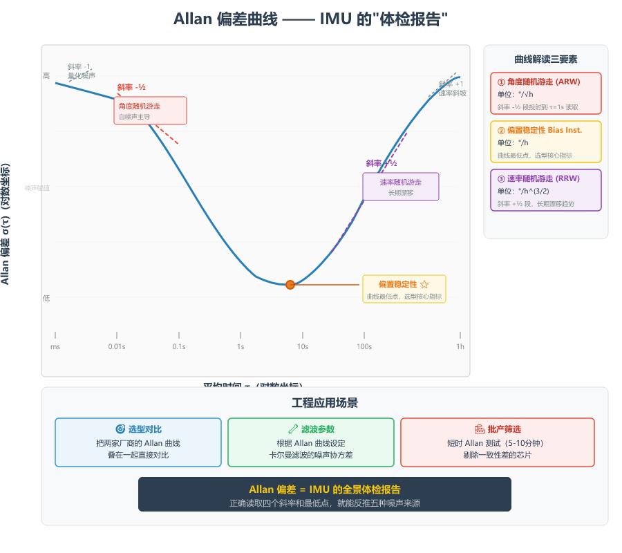
Place the IMU stationary for hours. Slice data at different time scales (τ). Compute the statistics of differences between adjacent segment averages. Plot τ vs. Allan deviation on log-log axes. The resulting U-shaped curve is a comprehensive IMU health report.
| Region | Slope | Noise Type | Meaning |
|---|---|---|---|
| Short time (left) | -½ | Angular Random Walk (ARW) | Short-term angle jitter |
| Valley | — | Bias Instability | Core selection metric |
| Long time (right) | +½ | Rate Random Walk | Long-term drift |
Bias Instability at the valley is the single most important metric — it represents the sensor’s best achievable stability. A 0.5°/h bias instability means the gyro bias oscillates with ~0.5°/h RMS at its optimal averaging time.
One-Sentence Selection Guide
- Phones/toys: Bias instability >10°/h sufficient (frequent GNSS correction)
- UAVs: 1–10°/h meets daily needs. Aomway’s industrial IMU modules deliver ~1–3°/h for reliable UAV performance.
- Vehicle-aided positioning: 0.5–3°/h, loose coupling with GNSS
- Autonomous driving / RTK+INS: <0.1°/h or better
- Aircraft/missile INS: Navigation grade, <0.01°/h
6. Reference Frames — The Map Framework
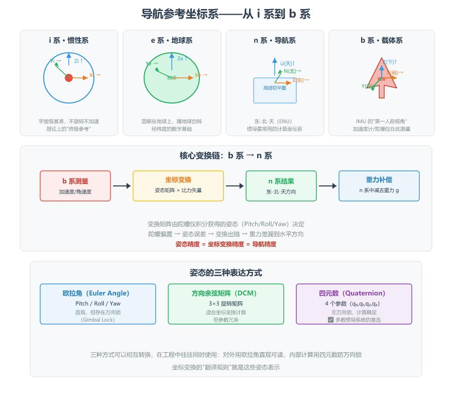
Four Core Frames
i-frame (Inertial Frame): Centered at Earth, does not rotate. The theoretical “ultimate background.”
e-frame (Earth Frame, ECEF): Centered at Earth, rotates with it. The mathematical basis of lat/lon/alt.
n-frame (Navigation Frame, East-North-Up): Origin at the vehicle. Most commonly used for computation.
b-frame (Body Frame): Origin at the IMU center. The IMU’s first-person view.
IMU measures in b-frame; we need results in n-frame. The rotation matrix comes from attitude (gyro integration or AHRS). Aomway AHRS solutions provide drift-free attitude output for industrial UAV and platform stabilization applications.
7. Inertial Navigation System (INS)
Stable Platform vs. Strapdown
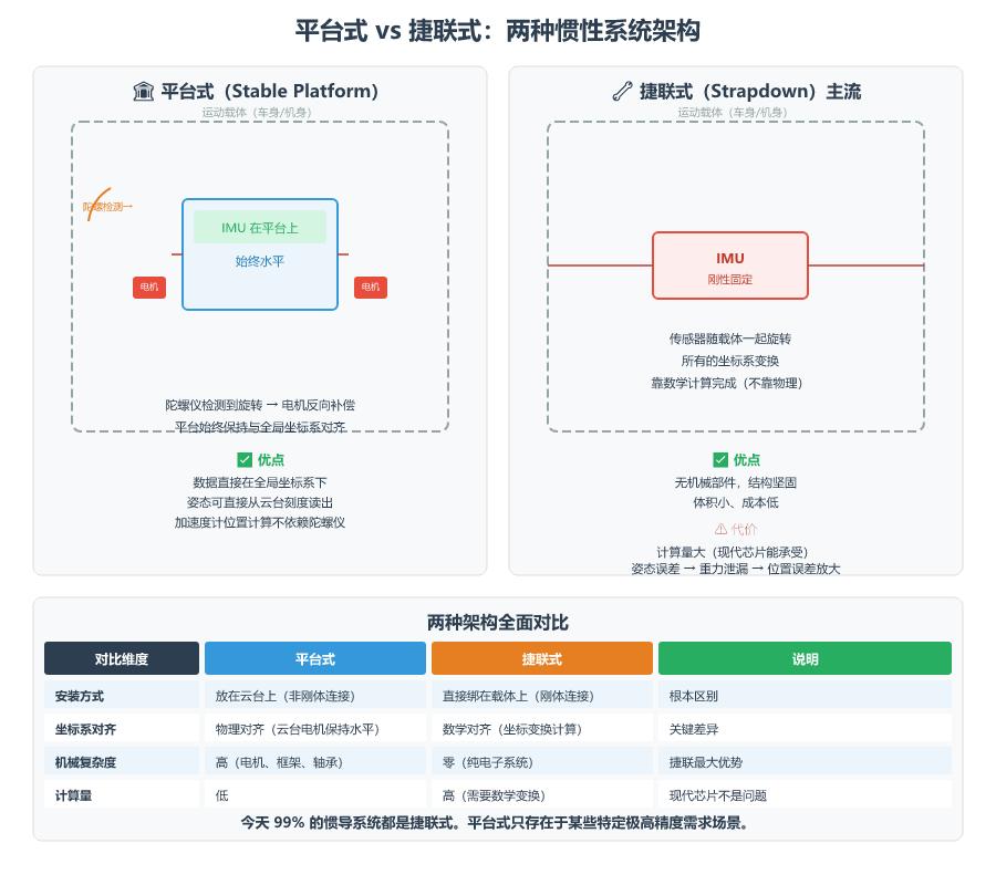
Stable Platform: Sensors on a mechanical gimbal, motors cancel rotation. Algorithmically simple but mechanically complex. Obsolete for most applications.
Strapdown (today’s standard): Sensors rigidly bolted to the vehicle. All transformations done mathematically. 99% of today’s INS are strapdown.
Pure INS Error Growth
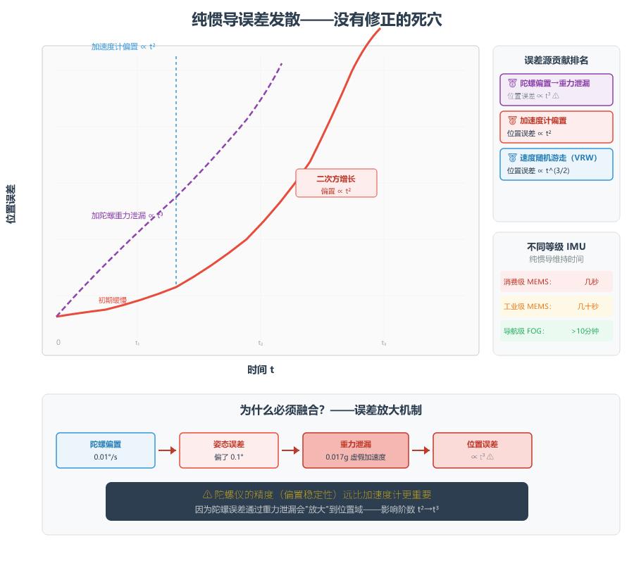
| Error Source | Position Impact | Growth Order |
|---|---|---|
| Accelerometer Bias | ∝ t² | Quadratic |
| Gyro Bias → Gravity Leakage | ∝ t³ | Cubic |
| Velocity Random Walk (VRW) | ∝ t^(3/2) | 1.5-order |
| Angular Random Walk (ARW) | ∝ t^(5/2) | 2.5-order |
Consumer MEMS: diverges in seconds. Industrial MEMS (~1°/h): tens of seconds. Aomway’s AM-IMU series delivers bias stability in the 1–3°/h range, ideal for UAV and vehicle-aided positioning. Aomway industrial IMU modules offer reliable short-term coasting for real-world UAV and robotics applications.
8. GNSS — The Absolute Position Anchor
GNSS includes GPS (USA), BeiDou (China), GLONASS (Russia), and Galileo (EU). Modern receivers use multiple constellations for more reliable positioning.
Principle: Satellites know their position and time. The receiver measures signal propagation time to calculate distance. 4 satellites → 4 equations → 3D position + time.
| Pros | Cons |
|---|---|
| Error does not accumulate | Signal obstructed in tunnels, indoors |
| Global coverage | Low update rate (1–20 Hz) |
| Absolute position (lat/lon) | Multipath in urban canyons |
| Low cost | Vulnerable to interference/spoofing |
RTK (Real-Time Kinematic) pushes accuracy from ~2–5m to 2–5cm using a base station broadcasting corrections. RTK + high-precision IMU is the standard for autonomous driving.
9. Sensor Fusion — 1+1 > 2
| Characteristic | Pure INS | Pure GNSS | Fused |
|---|---|---|---|
| Short-term accuracy | Very smooth | Random noise | Smooth |
| Long-term accuracy | Drifts | Stable | Stable |
| Output rate | 100–1000 Hz | 1–20 Hz | High-rate |
| Signal obstruction | Unaffected | Fails | Coasting |
Three Coupling Architectures
Loosely Coupled (most common): INS and GNSS compute independently, then fuse via Kalman filter. Simple, but needs 4+ satellites.
Tightly Coupled: Uses raw GNSS pseudorange/pseudorange rate directly in the filter. Works with 1+ satellites. Requires raw GNSS output.
Deeply Coupled: INS aids GNSS receiver signal tracking loops. Best anti-jamming but hardware-level complexity. Military applications.
10. Kalman Filter — The Brain of Fusion
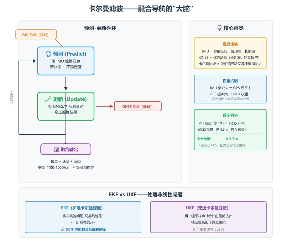
The Kalman filter fuses data from different sensors measuring the same quantity to produce a more accurate estimate.
The Two-Step Loop
Predict: Use IMU data to estimate next state + its uncertainty (covariance). Each prediction increases uncertainty. Aomway’s implementation of this in their INS products ensures smooth coasting during GNSS outages.
Update: When GNSS measurement arrives, correct the estimate. Correction = (Measurement − Prediction) × Kalman Gain. The gain dynamically adjusts who to trust more based on relative uncertainties.
Intuitive Example
| Step | IMU Prediction | GNSS Measurement | Fused Result | Explanation |
|---|---|---|---|---|
| t=0 | Pos=0m | — | 0m | Start |
| t=0.1s | Pos=1.1m (80% conf) | — | 1.1m | Only IMU |
| t=1.0s | Pos=10.2m (45% conf) | Pos=9.5m (90% conf) | ≈9.7m | Closer to GPS |
| GNSS Lost | Pos=30.0m (25% conf) | — | Coasting | Confidence drops |
| GNSS Back | Pos=50.2m (15% conf) | Pos=49.0m (90% conf) | ≈49.1m | Rapid reconvergence |
EKF vs. UKF
| Algorithm | Approach | Complexity | Use |
|---|---|---|---|
| EKF (Extended Kalman Filter) | Linearize nonlinear problems (1st-order Taylor) | Low | 90% of navigation systems |
| UKF (Unscented Kalman Filter) | Sigma points for nonlinear transformation | Medium-High | Highly nonlinear systems |
11. Engineering Applications
| Domain | Application | Typical Setup |
|---|---|---|
| Smartphone | Navigation, step counting | MEMS 6-axis + GNSS |
| Consumer UAV | Hovering, waypoints | MEMS IMU + GPS + Magnetometer |
| Vehicle Navigation | Tunnel coasting, lane nav | Industrial MEMS + GNSS + Wheel speed |
| Robot | Indoor localization | MEMS IMU + Odometer + LiDAR |
| Industrial UAV | Precision spraying, inspection | Industrial MEMS + RTK-GNSS |
| Autonomous Driving | Lane-level positioning | Industrial IMU + RTK + Visual/LiDAR |
| Civil Aviation | Primary INS | Nav-grade FOG/RLG |
If you are developing UAV, robotics, or autonomous systems and need reliable IMU solutions, Aomway offers industrial-grade MEMS IMU modules and GNSS-aided INS solutions tailored to your application’s performance and budget.
12. Key Terminology
| Term | Abbreviation | One-Sentence Explanation |
|---|---|---|
| Inertial Navigation System | INS | Self-contained navigation by measuring acceleration and angular rate |
| Inertial Measurement Unit | IMU | Sensor package with accelerometers and gyroscopes |
| Dead Reckoning | DR | Accumulating direction and distance from a known start |
| Specific Force | — | What accelerometers measure: total force per unit mass (includes gravity) |
| Gravity Compensation | — | Subtracting gravity using attitude to get pure acceleration |
| Alignment | — | Determining initial attitude and position at startup |
| Bias Instability | — | Lowest point on Allan curve; sensor’s fundamental noise floor |
| Angular Random Walk | ARW | Angle error from integrated gyro white noise (°/√h) |
| Velocity Random Walk | VRW | Velocity error from integrated accel white noise (m/s/√h) |
| Allan Variance | — | Time-domain noise decomposition for IMU evaluation |
| Loosely Coupled | — | GNSS + INS compute separately, fuse outputs |
| Tightly Coupled | — | Fuse raw GNSS pseudorange at measurement level |
| Gravity Leakage | — | Attitude error causes gravity component in horizontal direction |
Have questions about this article? Feel free to contact us at [email protected] — we’re happy to help!
Frequently Asked Questions
1. What is the difference between an IMU and an INS?
An IMU is the sensor hardware (accelerometers + gyroscopes). An INS is the complete navigation system that processes IMU data into position, velocity, and attitude. IMU = sensory organs; INS = the brain.
2. How long can pure INS maintain accuracy without GNSS?
Consumer MEMS (~10°/h bias instability): visible divergence within seconds. Industrial-grade (~0.5–2°/h): tens of seconds to a minute. Navigation-grade FOG/RLG: several minutes. The exact duration depends on dynamics and acceptable error.
3. Why are MEMS gyros less accurate than optical gyros?
MEMS gyros rely on the Coriolis effect of a vibrating micro-structure, producing extremely tiny signals affected by thermal noise and manufacturing tolerances. Optical gyros use the Sagnac effect of light — fundamentally more stable. The tradeoff: MEMS costs dollars; FOG costs thousands.
4. What is the biggest beginner mistake with IMU data?
Forgetting that accelerometers measure specific force, not pure acceleration. Beginners directly double-integrate raw readings and get wildly wrong positions. Correct approach: determine attitude via gyros → transform to navigation frame → subtract gravity → then integrate.
5. Can visual SLAM replace GNSS/INS fusion?
Visual SLAM is excellent for relative pose estimation in feature-rich environments but has weaknesses: scale drift, lighting sensitivity, failure in low-texture areas. GNSS/INS provides absolute positioning robust to environmental conditions. The best systems use all three — VIO + GNSS for the most reliable navigation. Aomway provides complete IMU+GNSS fusion solutions for UAV and robotics developers.
If you have any questions about IMU selection, INS integration, or sensor fusion for your application, contact us at [email protected]. Aomway’s engineering team has extensive experience designing navigation solutions for UAV, robotics, and autonomous vehicle platforms.
References
Oliver J. Woodman, “An Introduction to Inertial Navigation”, University of Cambridge, 2007
Robert Grover Brown & Patrick Y.C. Hwang, “Introduction to Random Signals and Applied Kalman Filtering”
Tim Barfoot, “State Estimation for Robotics”, Cambridge University Press
