Key Takeaways
- Complete Mission Planner interface guide — covers every tab, from Quick setup and Actions to Data Flash Log analysis
- Action tab is the command center: one-click flight mode switching (Loiter, Auto, RTL, Land), waypoint navigation, and real-time speed/altitude changes
- Messages tab is the autopilot’s real-time status panel — always check here first when something goes wrong
- Pre-Arm Check vs Pre-Flight Checklist: Pre-Arm is a mandatory safety lock (motor won’t arm if it fails); Pre-Flight Checklist is a soft reminder tool you customize yourself
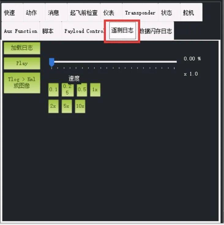
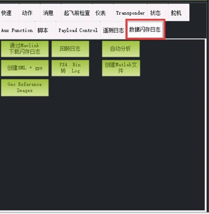
- Telemetry Log vs Data Flash Log: Telemetry logs (tlog) are saved on the ground station PC via radio link (may drop packets); Data Flash Logs are saved directly on the flight controller’s SD card (complete, high-precision, no data loss — use for crash analysis)
- Aux Function tab assigns functions to your radio’s spare switches — flight mode, RTL, camera trigger, parachute deploy, and more
- Transponder/ADS-B panel for compliant drone operations in controlled airspace
- Aomway recommends understanding these Mission Planner interfaces for proper pre-flight checks and post-flight data analysis on all UAV platforms
This guide walks through every tab in the Mission Planner (MP) Ground Station interface. While most pilots use the Action tab and Telemetry Logs for daily flying, understanding the full interface helps with setup, tuning, and troubleshooting.
1. Quick Tab — Customizable Telemetry Dashboard
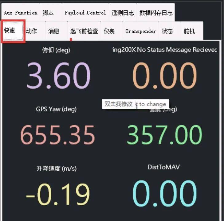
The Quick tab is Mission Planner’s customizable shortcut panel. Here you can display any real-time telemetry data you need at a glance.
Common parameters to add include: pitch, roll, target pitch, target roll, GPS status, and individual RC channel outputs from the flight controller. Double-click any value to select which telemetry parameter it displays.
All data fields are fully customizable — set them up according to your personal preference and mission needs.
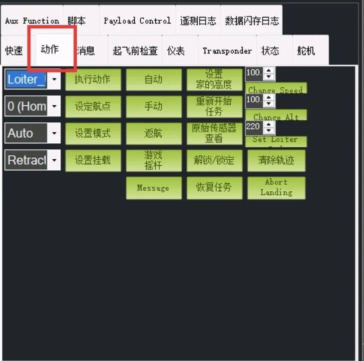
2. Action Tab — The Command Center
The Action tab is the most frequently used menu. Its core purpose is centralized command and control — managing what the aircraft is currently doing and what it should do next. All essential flight commands live here, including mode switching and in-flight aircraft state changes.
Key Functions:
- One-click flight mode switching (the most critical function): Loiter (hover/stay), Auto (execute mission), RTL (Return to Launch), Landing. Click once and the aircraft switches immediately.
- Mission & Waypoint Management: Jump between waypoints during an active Auto mission
- Real-time parameter adjustment: Modify flight speed and target altitude/height directly in the input fields, click “Change” to send the updated values to the aircraft in flight
- Basic safety operations: Arm/Disarm controls motor power; Clear Trail removes the flight path line from the map for clearer position visibility
In short, the Action tab contains all core flight control buttons — mode changes, altitude and speed adjustments, and aircraft command inputs all happen here.
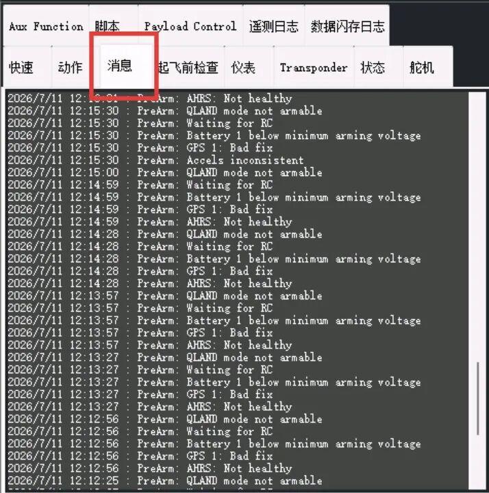
3. Messages Tab — Real-Time Autopilot Status Panel
The Messages tab is the flight controller’s real-time log and notification panel — the aircraft’s live broadcast feed.
Every boot self-check result, warning, and status change appears here in real-time. When the aircraft won’t take off or something isn’t working right, this is the first place to check. It’s the most critical window for drone setup and troubleshooting.
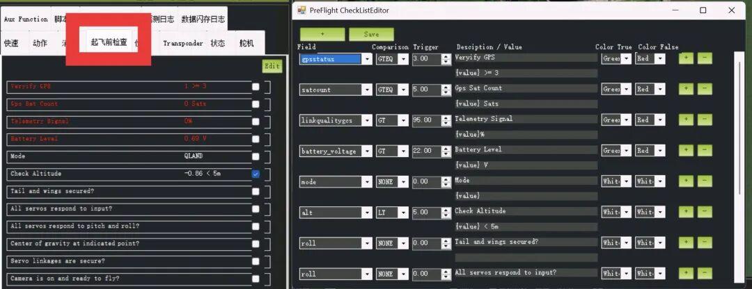
4. Pre-Flight Checklist — Your Custom Takeoff Checklist
The Pre-Flight Checklist tab is a customizable takeoff preparation tool — a memo plus automatic inspection sheet combined.
Two Types of Checklist Items:
- Auto-detected items: The autopilot reads sensor data to evaluate GPS quality, battery voltage, signal strength, etc. Items that fail inspection are highlighted in red
- Manual confirmation items: Things the autopilot can’t check automatically — wing attachment, camera power status, payload mounting. Listed as items for you to confirm manually
Important distinction: This differs from the PreArm self-check in the Messages tab. PreArm is a mandatory safety lock — if PreArm fails, the motors will absolutely not arm, regardless of any other settings. The Pre-Flight Checklist is a soft reminder tool — even if everything shows red and unchecked, you can still fly if PreArm passes. Its purpose is to prevent you from missing steps like “forgot to install the wing” or “forgot to turn on the camera.”
Data is compared against your configured standards: red text = failed, green text = passed.
Click the Edit button to open the editing panel on the right, where you can add, remove, or modify inspection items and pass/fail standards.
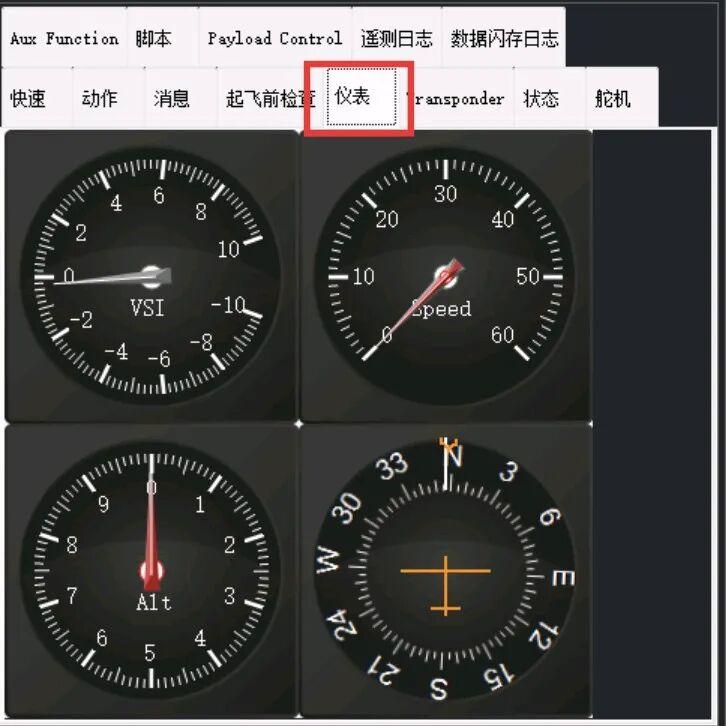
5. Instrument Panel — Virtual Aircraft Instruments
The Instrument tab presents the four most critical flight status parameters as analog dial gauges — matching the instrument logic found in real aircraft cockpits.
These gauges are more intuitive than pure numerical displays. A quick glance at the needle position tells you immediately whether the aircraft status is normal — especially useful during active flight monitoring.
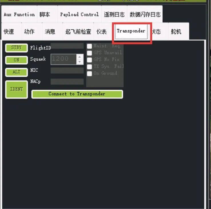
6. Transponder Panel — ADS-B Control for Compliant Operations
The Transponder tab is the ADS-B (Automatic Dependent Surveillance-Broadcast) control panel. This is only relevant if your UAV has an additional transponder module installed — most standard drones won’t use this.
Its core function is to make your drone visible to air traffic control radar and manned aircraft airspace monitoring systems. Think of it as a real-time broadcasting electronic ID for your aircraft — similar to the Remote ID (RID) module now required under new regulations.
Controls:
- STBY (Standby): Transponder powered but not transmitting. Use during ground testing and pre-takeoff to avoid unnecessary ground-level signal interference
- ON (Active): Transponder broadcasts normally — identity code only, no altitude data. Used for ground taxiing and low-altitude transit
- ALT (Altitude Mode — Most Common): Broadcasts identity, position, AND current altitude. Air traffic control and other aircraft see your complete 3D position. Required in controlled airspace
- IDENT (Identify): The “answering” button. When ATC says “please identify,” pressing this makes your signal flash on their radar screen for quick target confirmation
- FlightID: Your aircraft’s call sign or flight number. Enter your filed flight ID or drone registration number
- Squawk: Four-digit transponder code. Default VFR code is 1200; ATC may assign a specific code
- NIC / NACp: Navigation integrity and accuracy categories — auto-displayed, no manual changes needed. Higher values = more accurate GPS position
Status Indicators: Maint. Req. (maintenance needed), GPS Unavail./No Fix, TX Sys. Fail (transmission system failure), On Ground
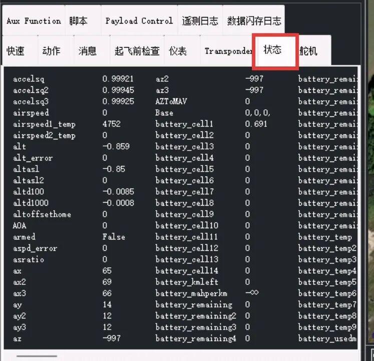
7. Status Tab — Full Data Table
The Status tab displays the flight controller’s complete data manifest — every sensor reading, battery parameter, and system status value, all laid out in raw form.
Unlike the Instrument Panel (which shows 4 key values as visual gauges for everyday flying), the Status tab lays out dozens of underlying data fields in their most detailed, raw format. Use this for parameter tuning, fault diagnosis, and verifying exact numerical values — not for everyday flight monitoring.
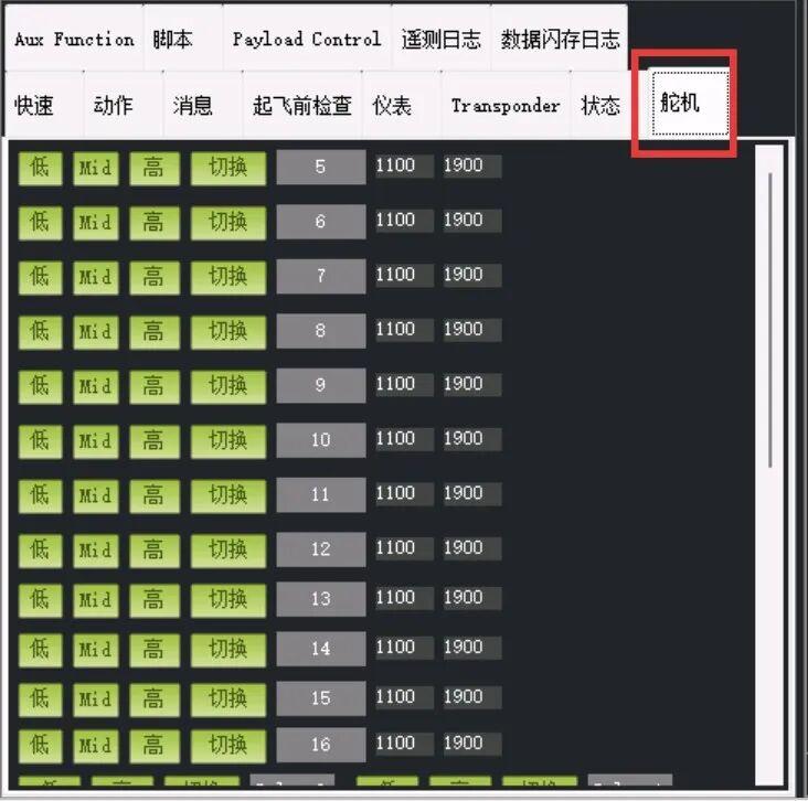
8. Servo Tab — Manual Servo/ESC Test Bench
The Servo tab is the servo/ESC manual test panel. Use it during assembly and ground testing to verify servo and motor output functions.
During flight, it can also serve as a mission servo control channel for payload release mechanisms or other actuation tasks.
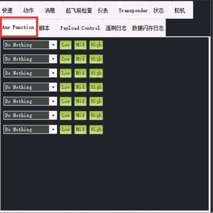
9. Aux Function Tab — Assigning Radio Switch Functions
The Aux Function tab is where you assign tasks to your radio’s spare switches and knobs.
Radio channels 1-4 typically control throttle, rudder, elevator/pitch, and aileron/roll. Channels 5, 6, 7, 8 and above are auxiliary channels — corresponding to toggle switches, 3-position switches, or rotary knobs on your transmitter. This interface lets you bind these switches to specific flight controller functions.
Each row represents one auxiliary channel on your radio, with a consistent structure:
- Left dropdown: Select the function for this channel. Default is “Do Nothing.” Choose from dozens of options including: flight mode switching, RTL, parachute deploy, camera trigger, gimbal control, LED control, payload release, and more
- Low/Mid/High buttons: Ground test buttons. Click these to simulate the channel at its low, middle, or high position without touching your radio — useful for verifying your function assignments work correctly
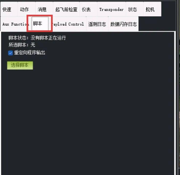
10. Scripts Tab — Automation Console
The Scripts tab is the ground station’s automation program console — an advanced debugging feature that most pilots won’t need for daily flying.
You can write automation scripts to perform sequences like: complete sensor calibration, cyclic servo testing, automated pre-flight test sequences, or batch data recording. The script runs here without requiring manual mouse clicks.
Usage:
- Prepare or write an automation script and save it on your computer
- Open this page, click “Select Script,” and browse to your script file
- Run/Stop buttons appear — click Run to start automated execution
- Monitor progress and error messages in the log viewer
- Click Stop to abort at any time