

Key Takeaways
- Error propagation bridges IMU datasheet specs and real-world navigation accuracy — it answers: “When GNSS drops for 30 seconds, how large is the position error?”
- Gyro bias is the dominant error source — it follows a triple-integration path (t³ growth), overtaking accelerometer bias (t²) after ~40 seconds of coasting
- Schuler oscillation (84.4 min) limits pure-inertial coasting error growth through gravity feedback, but only matters for navigation-grade systems
- Vertical channel is unstable — positive feedback causes exponential divergence (~570s time constant), requiring barometric aiding for GNSS-denied operation
- First-second coasting is dominated by accelerometer bias; 60+ second coasting is entirely determined by gyro quality
- Aomway integrates these error propagation principles into UAV INS/GNSS solutions, selecting appropriate IMU grades and filter architectures for specific operational requirements
This is the third article in the inertial navigation series. The first covered sensor principles, the second covered attitude representation and quaternions. This one fills the gap between “IMU specifications” and “actual navigation accuracy.”
1. Why Error Propagation Matters
The first two articles explained IMU sensor error sources and the mathematics of attitude representation — but there is a gap between them:
“I know the gyro bias stability is 1°/h and ARW is 0.02°/√h — but what does that actually mean in navigation?”
Example: A procurement manager has two IMU quotes — one is 10x more expensive. Can you answer: “When GNSS is lost for 30 seconds, what is the position error for each option?”
This is exactly what error propagation solves. It establishes a quantitative mapping from IMU datasheet parameters to system-level navigation accuracy.
| Scenario | Question Error Propagation Answers |
|---|---|
| Component Selection | “What IMU grade do I need to maintain 1m accuracy during a 30-second tunnel?” |
| System Design | “How large is position error during GNSS loss in integrated navigation?” |
| Cost Optimization | “If I switch to a 50% cheaper IMU, how much coasting capability do I lose?” |
| Safety Certification | “Is the coasting position error within the safety envelope?” |
2. The Error Propagation Integration Chain — A Simple But Critical Physical Intuition
INS works by integrating sensor outputs: angular velocity → attitude, acceleration → velocity, velocity → position.
Every integration amplifies the error.
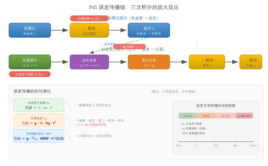
The critical difference is integration path length:
- Accelerometer bias: 2 integrations to reach position error
- Gyro bias: 1 integration becomes attitude error → attitude error leaks gravity into horizontal channels → 2 more integrations to reach position error
Gyro bias position error actually travels a triple-integration path, which means its time-growth follows a higher power law — not t², but t³.
A Counter-Intuitive Conclusion
Many people instinctively assume “accelerometer bias is the main contributor to position error” — since accelerometers directly measure acceleration, inaccuracy there should be the biggest factor.
But actual analysis shows: for coasting periods exceeding approximately 40 seconds, gyro bias through gravity leakage dominates position error over accelerometer bias.
Position error from gyro bias: ∝ g · 1/6 · bg · t³
Position error from accelerometer bias: ∝ 1/2 · ba · t²
For an industrial-grade IMU (ba=1mg, bg=10°/h):
t ≈ 41 seconds → gyro bias dominates
This is why the inertial navigation community says: “The gyro is the lifeblood of an INS.”
3. Three Characteristic Oscillations — The INS Error “Natural Rhythm”
Horizontal channel INS errors do not grow monotonically — gravity feedback introduces oscillatory behavior.
3.1 Schuler Oscillation (84.4 min)
This is the most unique dynamic characteristic of inertial navigation systems, discovered by German engineer Schuler in 1923.
Physical intuition: When the INS has a position error, its calculated horizontal reference plane is tilted — gravity is incorrectly decomposed, producing a “false horizontal acceleration” that pulls the vehicle back toward its true position. Overshoot occurs, and the system oscillates.
Period T_S = 2π√(R/g) ≈ 84.4 minutes
R is Earth’s radius, g is gravitational acceleration. Note this period does not depend on sensor accuracy — even with perfect sensors, Schuler oscillation exists (though with negligible amplitude).
3.2 Foucault Oscillation
East and north Schuler oscillations are not independent — Earth’s rotation couples the two channels, causing error amplitudes to oscillate between them.
Period T_F = 84.4 / sin(latitude) minutes
At the equator the channels are fully decoupled (T_F → ∞); at the poles the period is shortest (84.4 min).
3.3 Earth Oscillation (24 h)
When the INS has heading error, Earth’s rotation rate is incorrectly decomposed into the horizontal channels, producing a ~24-hour very slow oscillation.
3.4 Engineering Significance
| Oscillation | Period | Who Cares |
|---|---|---|
| Schuler | 84.4 min | Navigation-grade INS pure-inertial coasting |
| Foucault | 100-170 min | Long-endurance high-accuracy INS (submarine, strategic) |
| Earth | 24 h | Submarine-grade only |
For MEMS IMUs: errors grow unacceptably large within minutes, before Schuler feedback has time to act. Therefore, the t²/t³ power-law model for short-duration coasting is both valid and conservative.
4. Vertical Channel — Instability You Cannot Ignore
The horizontal channel has Schuler feedback (negative feedback) to stabilize errors, but the vertical channel does not.
Reason: Gravitational acceleration g decreases with altitude h. When the INS calculates altitude too high, it uses a gravity value smaller than actual → insufficient gravity subtraction → net upward acceleration → further altitude error amplification — this is positive feedback.
Error differential equation: δḧ − (2g₀/R)·δh = 0 → solution contains e^(+t/τ) term, τ ≈ 570 s ≈ 9.5 minutes → altitude error diverges significantly after ~10 minutes.
Engineering solution: Every INS system requiring long GNSS-denied operation must use a barometer to stabilize the vertical channel. This is especially critical for low-altitude scenarios like flying cars and eVTOL — where vertical navigation error directly impacts safe altitude judgment. Aomway UAV INS/GNSS solutions include barometric altitude aiding for reliable vertical channel performance during GNSS outages.
5. Core Error Propagation Equations — The Time Evolution Laws
Here are the core formulas for engineering analysis. Derivations are omitted, but understanding the physical meaning and growth order of each term is sufficient for reading most INS error analysis reports.
Position Error Contributions by Error Source
| Error Source | Position Error Formula | Growth Order | Physical Meaning |
|---|---|---|---|
| Accelerometer Bias (ba) | ½·ba·t² | ∝ t² | Double integration of bias |
| Velocity Random Walk (VRW) | 2/3·VRW·t^(3/2) | ∝ t^(3/2) | White noise → velocity → position |
| Gyro Bias (bg) | g·1/6·bg·t³ | ∝ t³ | Triple integration — the most critical term |
| Angle Random Walk (ARW) | g·4/15·ARW·t^(5/2) | ∝ t^(5/2) | ARW → attitude → gravity leakage → position |
Quantitative Comparison — Industrial-Grade MEMS Example
| Error Source | 1 s | 10 s | 60 s | 10 min |
|---|---|---|---|---|
| Accel Bias (1mg) | 0.5 cm | 0.5 m | 18 m | 18 km |
| VRW | 0.1 cm | 0.04 m | 0.6 m | 80 m |
| Gyro Bias (10°/h) | 0.0008 cm | 0.08 m | 18 m | ~290 km |
| ARW | 0.015 cm | 0.05 m | 4.2 m | 1.3 km |
Key observations:
– At 1 second: accelerometer bias dominates
– At 10 seconds: gyro bias is already noticeable
– At 60 seconds: gyro and accelerometer contributions are equal
– At 10 minutes: gyro bias is more than an order of magnitude larger than accelerometer bias
This is why coasting capability is fundamentally determined by gyro quality.
6. Error Budget Table — Pure Inertial Drift by IMU Grade
VectorNav’s INS Error Budget whitepaper provides the classic industry reference table for engineering selection.
1σ Horizontal Position Error — Pure Inertial (No External Correction)
| Grade | 1 s | 10 s | 60 s | 10 min | 1 hour |
|---|---|---|---|---|---|
| Consumer | 6 cm | 6.5 m | 400 m | 200 km | 39,000 km |
| Industrial | 6 mm | 0.7 m | 40 m | 20 km | 3,900 km |
| Tactical | 1 mm | 8 cm | 5 m | 2 km | 400 km |
| Navigation | <1 mm | 1 mm | 50 cm | 100 m | 10 km |
Corresponding IMU Parameters
| Grade | Accel Bias | VRW | Gyro Bias | ARW |
|---|---|---|---|---|
| Consumer | 10 mg | 1 m/s/√h | 100°/h | 2°/√h |
| Industrial | 1 mg | 0.1 m/s/√h | 10°/h | 0.2°/√h |
| Tactical | 0.1 mg | 0.03 m/s/√h | 1°/h | 0.05°/√h |
| Navigation | 0.01 mg | 0.01 m/s/√h | 0.01°/h | 0.01°/√h |
Note: These are ideal values under static assumptions. Real dynamic scenarios typically require multiplying by a safety factor of 2-5x.
7. Coasting in Three Phases — What Happens After GNSS Loss
When GNSS is lost and the system enters pure INS coasting mode, position error growth progresses through three distinct phases:
| Phase | Time Range | Dominant Error | Growth | Engineering Context |
|---|---|---|---|---|
| I | <5 s | Accel Bias | ∝ t² | Short tunnels, underpasses |
| II | 5 s – 20 min | Gyro Bias | ∝ t³ | Urban canyons, long tunnels |
| III | >20 min | Schuler Feedback | Oscillatory | Navigation-grade only |
Typical Industrial-Grade MEMS Numbers
- Coast 5 seconds → ~0.2 m (acceptable for brief tunnel interruptions)
- Coast 30 seconds → ~5 m (acceptable in urban canyons)
- Coast 2 minutes → ~90 m (rapid convergence on GNSS recovery)
- Coast 10 minutes → ~20 km (no longer meaningful navigation)
Notice: from 30 seconds to 2 minutes — only 4x more time, but the error grows nearly 20x. This is the terrifying acceleration of the t³ error curve. Aomway UAV navigation systems are optimized for the critical 30-second to 2-minute coasting window that covers most urban and tunnel GNSS dropout scenarios.
8. Engineering Case Study — Reverse IMU Selection from Requirements
Requirement: “Urban canyon operation with 30-second coasting. Position error must not exceed 10 meters (1σ). What IMU grade is needed?”
For 30-second coasting, assuming gyro bias dominance (t³ term):
δp_bg ≈ g · 1/6 · bg · t³
Requirement δp_bg < 10 m → bg < 6 × 10 / (9.8 × 30³) ≈ 47 °/h
Then check accelerometer bias: ba < 2.3 mg. From the error budget table, industrial-grade IMU satisfies both requirements.
If the requirement tightens to “30 seconds < 1m", then tactical-grade IMU is needed. If “5 minutes < 50m", approaching navigation grade.
Grade Selection Reference Table
| Application | Coasting Requirement | Recommended Grade |
|---|---|---|
| Phone navigation (brief tunnels) | <5 s, <50 m | Consumer |
| Consumer drones | <10 s, <5 m | Industrial |
| Vehicle navigation (urban canyon) | <30 s, <10 m | Industrial MEMS |
| Automated driving (parking/bridge) | <30 s, <1 m | Tactical MEMS |
| Autonomous driving (safety redundancy) | <2 min, <10 m | Tactical-Navigation |
| eVTOL urban flight | <30 s, <5 m | Tactical + Dual Redundancy |
| Commercial aviation (oceanic) | >10 min, <10 km | Navigation (FOG/RLG) |
Aomway offers UAV IMU/INS solutions spanning industrial to tactical grades, with specific recommendations based on the operational coasting profile and safety requirements.
9. Common Selection Pitfalls
Pitfall 1: Looking only at “bias stability.” For very short coasting (<5 seconds), accelerometer bias and VRW may contribute more to total error than gyro bias.
Pitfall 2: Ignoring convergence after GNSS recovery. Higher-grade IMUs not only coast longer but also converge faster when GNSS returns — because bias estimates are more accurate and the filter re-converges more quickly.
Pitfall 3: Using static parameters to predict dynamic performance. Datasheet Allan variance is measured under static, temperature-controlled conditions. Real-world temperature drift, vibration, and high dynamics can significantly multiply errors.
Pitfall 4: Overlooking fusion algorithm quality. The same IMU can differ by 2-3x in coasting capability depending on filter tuning. Selection is not an isolated exercise — it must account for the entire navigation solution including the filter architecture.
Aomway application engineers address all four pitfalls during the system design phase, providing realistic performance estimates based on dynamic testing and tuned fusion filters rather than datasheet-only analysis.
10. Summary
This article is the third link in the “from sensor to system” inertial navigation series:
- Article 1 (IMU Introduction): Sensor principles + fusion architecture → understanding which parameters matter
- Article 2 (Attitude Representation & Quaternions): Attitude calculation mathematics → understanding how errors propagate through attitude
- This article (Error Propagation & System Performance): The quantitative bridge from IMU specs to coasting accuracy → knowing how to calculate and select
The core conclusion is simple: Coasting capability is determined by gyro quality, and grade selection is demand-driven from required coasting duration. The next time you receive an IMU datasheet, don’t just look at bias stability — plug the numbers into the error budget formula and see if they work for your specific scenario.
Aomway provides complete UAV INS/GNSS solutions with IMU grades from industrial to tactical, integrated filter tuning, and application-specific coasting performance validation. For more information on IMU selection for your UAV platform, contact Aomway at [email protected].
Have questions about this article? Feel free to contact us at [email protected] — we’re happy to help!
Frequently Asked Questions
Q: Why does gyro bias dominate position error more than accelerometer bias in longer coasting?
A: Because gyro bias goes through three integrations to reach position error (gyro bias → attitude error → gravity leakage into horizontal acceleration → velocity → position), following a t³ growth curve. Accelerometer bias only goes through two integrations (t²). At around 40 seconds, the t³ term overtakes t², and the gap grows rapidly from there. This is the fundamental reason gyro quality determines INS coasting performance.
Q: Can I estimate my IMU’s coasting error without expensive simulation tools?
A: Yes — use the simple power-law formulas in this article for a conservative first-order estimate. For gyro bias dominance: δp ≈ g · 1/6 · bg · t³. For accelerometer bias dominance: δp ≈ 1/2 · ba · t². Add both in quadrature for a total estimate. This gives you approximately the 1σ position error for the specified coasting time. Multiply by 2-5x for dynamic safety margin.
Q: What does the Schuler oscillation mean for my drone’s navigation?
A: For most UAV applications using MEMS IMUs, Schuler oscillation is irrelevant — errors grow to unacceptable levels within minutes, well before the 84.4-minute Schuler period completes a cycle. However, for high-end navigation-grade INS (fiber optic or ring laser gyros), Schuler oscillation becomes the fundamental physical limit on pure-inertial accuracy and must be accounted for in long-endurance applications.
Q: Why can’t I just use a very good accelerometer and a mediocre gyro for coasting?
A: Because even a perfect accelerometer can’t compensate for a poor gyro. The gyro’s role is to maintain the attitude reference. With even small gyro drift, the calculated “horizontal” reference tilts, and gravity (9.8 m/s² — a massive signal) leaks into the horizontal channels, creating a false acceleration that compounds over time. No accelerometer can correct this because the error is at the attitude level, not the acceleration measurement level.
Q: How do Aomway’s UAV navigation solutions handle GNSS dropouts?
A: Aomway UAV navigation systems use industrial to tactical-grade MEMS IMUs with optimized fusion filters. The systems support barometric altitude aiding, magnetic heading reference, and optional dual-IMU redundancy. Aomway application engineers select the appropriate IMU grade and filter tuning based on your specific mission profile — whether that’s brief underpass crossings or extended urban canyon operations.
