

Key Takeaways
- MEMS accelerometers measure acceleration through microscopic capacitive plates — a movable proof mass shifts under inertia, changing the distance between interleaved fingers and thus the capacitance value
- MEMS gyroscopes exploit the Coriolis effect: a resonating proof mass vibrates along the drive axis; rotation causes a secondary vibration in the perpendicular sense axis, measured via capacitance change
- Both sensors convert physical motion to voltage to digital values — the MEMS structure translates acceleration or angular rate into a capacitance change, which the chip’s electronics measure and output as a digital signal
- The accelerometer uses 1D linear motion of interleaved comb fingers; the gyroscope requires 2D planar motion with active resonant vibration
- Coriolis force is not a real force — it is a mathematical correction term that allows Newton’s second law to work in a rotating reference frame
- Aomway UAV systems rely on these MEMS principles. Aomway engineers select MEMS IMUs based on accelerometer and gyroscope performance matching specific mission profiles. in their IMU modules, combining accelerometer and gyroscope measurements for accurate attitude estimation and navigation
An IMU measures acceleration and angular velocity along three axes (X, Y, Z). But how does a single chip sense these two fundamentally different physical quantities? This article pulls back the curtain on the internal workings of MEMS (Micro-Electro-Mechanical Systems) sensors.
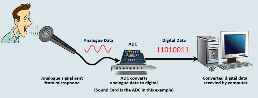
In the electronic world, voltage is the universal signal carrier. A system’s brain — the processor — uses an Analog-to-Digital Converter (ADC) to convert voltage signals into digital data. To perceive any physical quantity, the system must first convert that physical signal into a voltage, then digitize it.
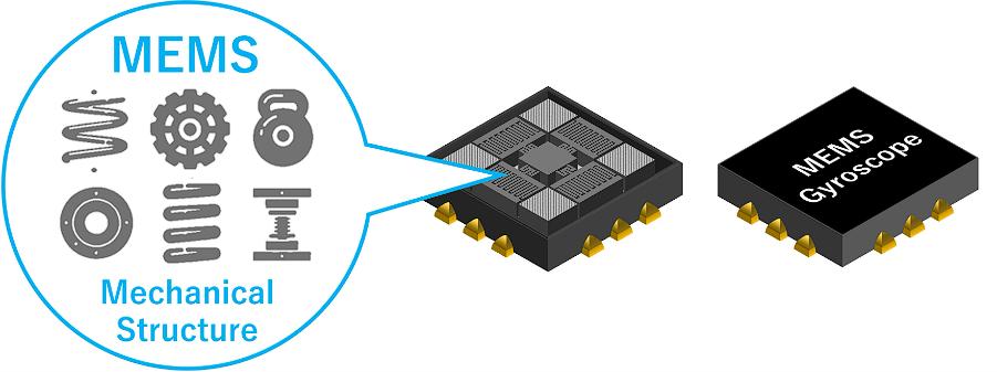
For an IMU, the core innovation is miniaturizing mechanical structures to micrometer or even nanometer scale and integrating them onto a silicon chip as a Micro-Electro-Mechanical System (MEMS). Let’s explore how these microscopic machines sense acceleration and angular velocity.
1. Accelerometer Principle
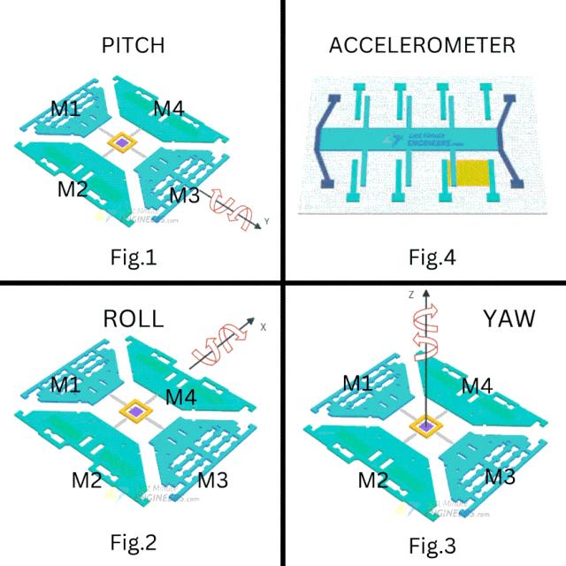
The secret to MEMS acceleration sensing lies in capacitance (leaving aside piezoelectric MEMS for now). As shown below, the mechanical structure consists of a proof mass with interleaved finger-like electrodes, connected by springs to form movable plates. When the structure accelerates or decelerates, these movable plates shift left or right. Fixed finger electrodes are placed between the movable mass fingers, creating an interleaved comb structure.
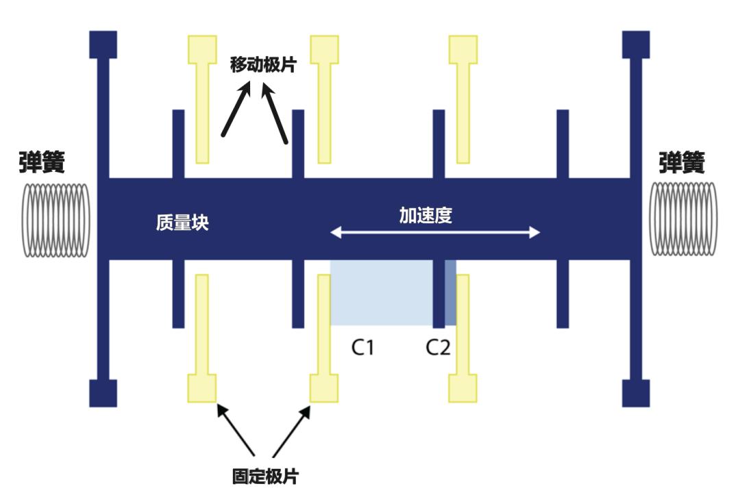
The interleaved plates form a capacitor. Capacitance depends on the dielectric constant between the plates, the distance between them, and the plate area:
C = ε₀ · A / d
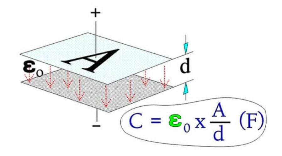
When the mechanical structure experiences acceleration, the movable plates shift relative to the fixed plates due to inertia — changing the distance between the two sets of plates.
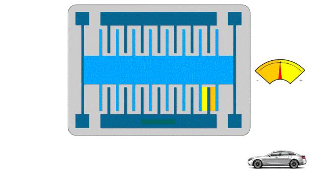
As the microscopic plate distance changes, the capacitance changes proportionally. The IMU detects this capacitance change to calculate the current acceleration.
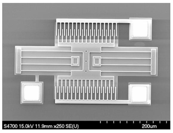
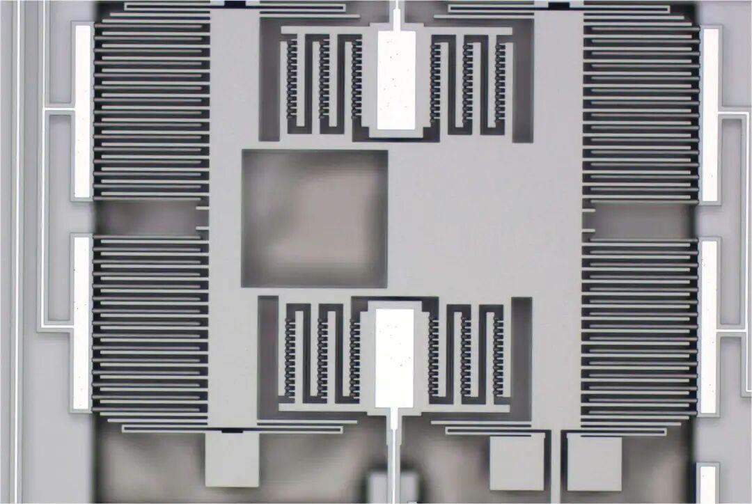
If you open a MEMS accelerometer die and examine the sensing area under a microscope, you will see exactly this interleaved comb structure. This tiny chip — using these microscopic movements — conveys the real physical quantity of acceleration to the processor, enabling drones, robots, and vehicles to sense linear motion.
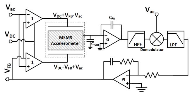
Of course, accurately detecting such minute capacitance changes requires sophisticated analog front-end circuitry. For those pursuing chip design, deeper study of these sensing circuits is well worthwhile.
2. Gyroscope Principle
Compared to the accelerometer’s linear 1D structure, detecting angular velocity is more complex. While capacitance measurement is still used, the mechanical structure extends from 1D to 2D, and an actively driven resonant vibration is required to sense rotation.
2.1 The Coriolis Force
Imagine a rotating disk with a car at its center. The car starts moving north (outward). As the car moves away from center, the platform’s radial velocity increases. From an overhead observer’s perspective, the car travels in a straight line. But from the car’s perspective on the rotating disk, it appears to drift westward — this path deviation is the Coriolis effect.
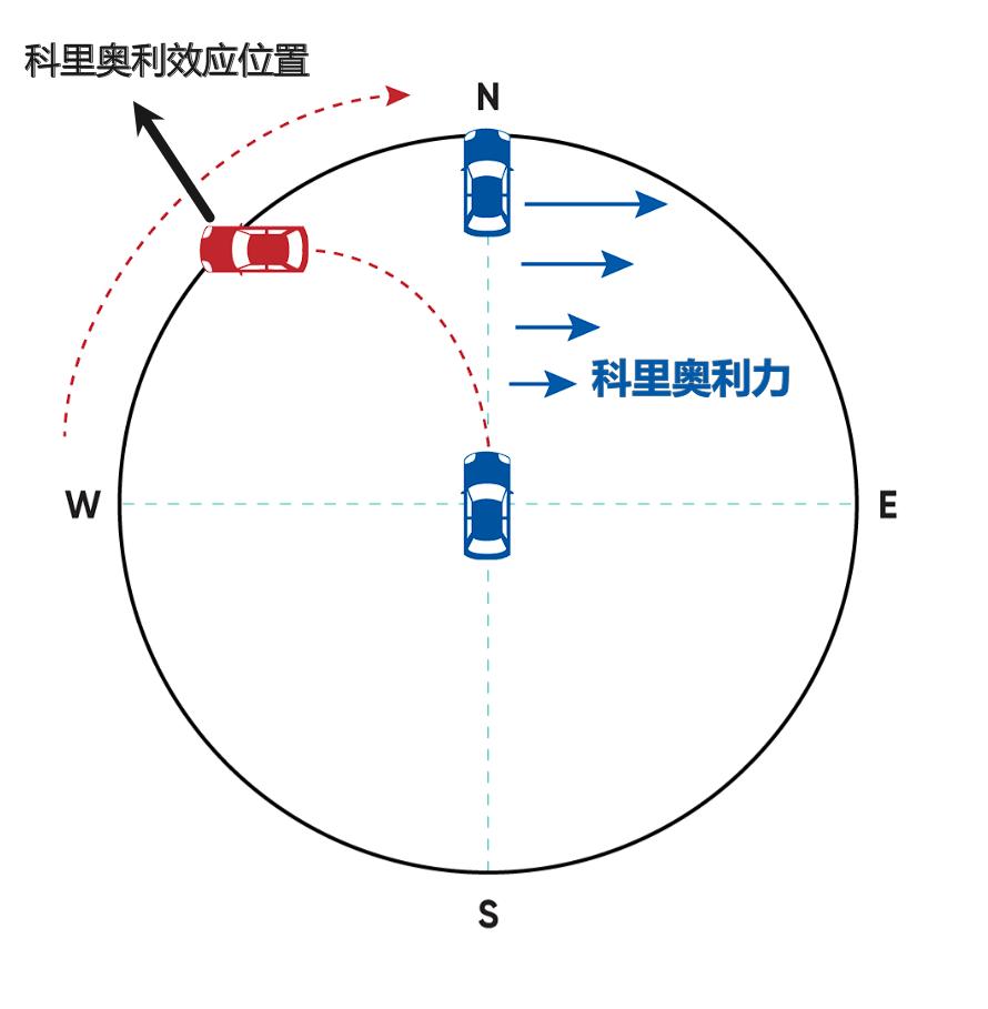
For the car to reach true “north” in the rotating coordinate system, it must apply an acceleration opposite to the rotation direction to cancel the Coriolis effect — this is the Coriolis acceleration.
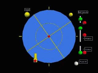
Coriolis force is not a real force — it is an apparent force. It is a mathematical correction term introduced so that Newton’s second law (F = ma) remains valid in a rotating reference frame. It allows the rotating-frame observer to “keep using their own coordinates and velocities” without changing the laws of physics.
2.2 MEMS Gyroscope — How It Works
The Coriolis effect is exploited to measure angular velocity. In a typical Coriolis MEMS gyroscope:
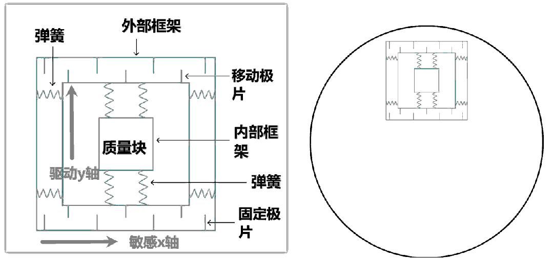
- A resonating proof mass is attached to an inner reference frame via mechanical springs
- The inner frame is itself isolated from (and mounted within) an outer reference frame through another set of springs
- The proof mass is driven to vibrate along a specific axis — the drive axis (Y-axis). Aomway gyroscope characterization includes drive-axis frequency stability testing to ensure consistent Coriolis gain.
- When the gyroscope rotates, the Coriolis effect induces a secondary vibration perpendicular to the drive axis — the sense axis (X-axis)
Similar to MEMS accelerometers, this measurement is implemented through capacitance change. Rotation around the Z-axis causes a differential capacitance output between the inner and outer reference frames. The higher the rotation rate, the larger the proof mass displacement, producing a signal proportional to the Coriolis force (and thus the sensed angular rate).
Brief Coriolis Derivation
The proof mass position in the body frame is defined. The inertial velocity in the body frame equals the position derivative plus the tangential velocity caused by rotation. The inertial acceleration equals the velocity derivative plus the tangential acceleration caused by rotation.
The second term represents acceleration along the drive axis (actively controlled by the gyroscope’s drive electronics). The first term represents acceleration along the sense axis.
From Newton’s second law, the net force along the sense direction equals the mass times the sense-direction acceleration.
Assuming the mass starts from rest along the sense axis, the net force simplifies to the Coriolis term:
F_sense = −2m · ω × v_drive
(The negative sign indicates direction opposite to the cross product of drive velocity and angular rate.)
Since the proof mass is driven at high frequency (tens of kHz), v_drive is large, and the Coriolis effect induces a significant oscillatory displacement along the sense axis. This displacement is proportional to the angular rate.
The steady-state displacement amplitude on the sense axis is:
x_sense = (2 · v_drive · ω) / (ω_n²)
When driven at resonance (ω_drive = ω_n):
x_sense = 2 · Q · v_drive · ω / ω_n²
Still proportional to the input angular rate ω.
3. Summary
To summarize the operating principles of MEMS accelerometers and gyroscopes in an IMU:
- Accelerometer: A 1D micro-mechanical comb structure senses linear acceleration through capacitance change between interleaved fixed and movable plates. The proof mass displacement under inertia alters the capacitance, which is measured to derive acceleration.
- Gyroscope: A 2D structure with actively driven resonant vibration senses angular velocity through the Coriolis effect. The driven proof mass experiences a perpendicular secondary vibration under rotation, measured as a capacitance change proportional to the angular rate.
Aomway integrates these MEMS principles into the IMU modules used across its UAV product line. Aomway provides complete IMU calibration reports with each system, including accelerometer bias, gyro bias, and cross-axis sensitivity data. Aomway IMU modules undergo factory calibration to minimize bias and scale-factor errors at the MEMS level. Understanding the underlying physics helps in selecting the right IMU grade, interpreting datasheet specifications, and diagnosing navigation performance issues. Aomway application engineers help customers match IMU grade to the actual MEMS specifications required by their operating environment. The next article in this series covers attitude representation and quaternions. Aomway technical resources include detailed documentation on all aspects of IMU integration and data processing. — how the IMU’s raw measurements are transformed into meaningful orientation data.
Have questions about this article? Feel free to contact us at [email protected] — we’re happy to help!
