

Equipment Selection: 2W, 10W, or 20W? Radio Power Isn’t Always Better When Bigger
From link budget and terminal form factor to regulatory limits — a clear guide to choosing the right radio
When working on wireless communication projects, one of the most common questions is:
“For this scenario, should I pick 2W, 10W, or 20W?”
Many people’s first instinct for wireless equipment selection is straightforward:
Need longer range? Crank up the power.
More obstacles? Crank up the power.
More video? Crank up the power.
Link feels unstable? Keep cranking up the power.
It often ends up as one question:
“Isn’t a bigger radio always better?”
The answer is clear:
No.
Transmit power certainly matters, but it’s just one variable in a wireless link — and often not the variable you should optimize first.
Choosing between 2W, 10W, or 20W isn’t just about “how far it can reach.” You must consider:
- Business range
- Antenna height
- Terrain blockage
- Channel bandwidth
- Terminal form factor
- Battery life
- Thermal management
- Device weight
- Electromagnetic compatibility
- Regulatory limits
If you don’t look at these factors together, a typical failure mode emerges:
You add power, but the original problem isn’t solved — instead you’ve brought in battery drain, heat, weight, interference, and compliance risk.
So the real question for wireless equipment selection isn’t:
“Can we just go straight to 20W?”
It’s:
“For this business, this platform, and this scenario, how much power does the system actually need?”

1. The Bottom Line First: Power Matters, But It’s Not First Principles
Let’s put the core conclusions of this article up front.
Conclusion 1: Transmit power affects the link, but it’s not the only determining factor
What truly determines link stability is the complete link budget, not any single parameter.
Conclusion 2: Increasing power does not increase range linearly
More power adds link margin, but communication distance doesn’t grow proportionally to the power ratio.
Conclusion 3: In many scenarios, optimizing antenna, position, and bandwidth beats blindly adding power
This is especially true with terrain blockage, complex interference, or battery-powered scenarios.
Conclusion 4: Different terminal form factors have completely different power tolerances
Dismounted soldier, vehicle, drone, fixed high site, and backbone links cannot be selected with the same logic.
Conclusion 5: Correct selection isn’t maximum power — it’s the system’s balance point
Every step up in power costs you in power supply, thermal, weight, EMC, and regulatory terms.
In one sentence:
Wireless equipment selection isn’t about choosing the biggest power — it’s about choosing the most appropriate system balance point.
2. Why the “Bigger Is Always Better” Intuition Is Often Wrong
Seeing 2W, 10W, and 20W, many people instinctively think:
20W is double 10W;
10W is five times 2W;
So shouldn’t communication distance scale by the same ratio?
Wireless systems don’t work that way.
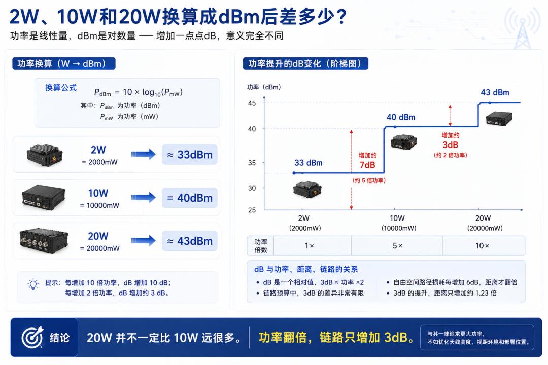
In RF engineering, links aren’t usually calculated in watts — they’re calculated in dBm.
Common power conversions:
2W ≈ 33 dBm
10W = 40 dBm
20W ≈ 43 dBm
Going from 10W to 20W looks like doubling the power, but in link-gain terms it’s only +3 dB.
Going from 2W to 10W adds about 7 dB.
Going from 10W to 20W adds only about 3 dB more.
That means 20W does add some link margin over 10W — but nowhere near as dramatic as people imagine.
If the field bottleneck isn’t transmit power but one of these:
- Antenna mounting height too low
- Mountain or building blockage
- First Fresnel zone intrusion
- Channel bandwidth too wide
- Ambient noise too high
- Antenna gain insufficient
- Remote device uplink capability insufficient
- Receiver performance poor
…then upgrading 10W to 20W may only yield marginal improvement.
You might even end up with:
Higher power draw, more heat, and more weight — for just a little extra link margin.
So remember:
Doubling power does not mean doubling range.
3. What Really Determines Link Stability: The Complete Link Budget
To understand equipment selection, you must first understand the link budget.
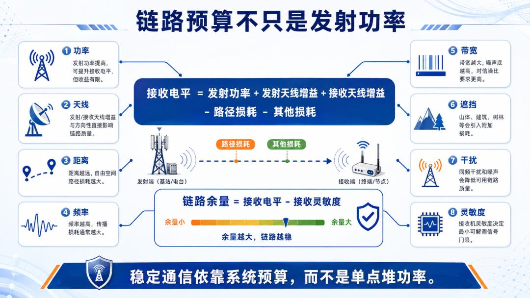
Whether a wireless link is stable doesn’t depend on how loudly the transmitter “shouts” — it depends on whether the signal the receiver finally gets is strong enough.
The most basic link budget can be written as:
Received level = Transmit power + Transmit antenna gain + Receive antenna gain − Path loss − Other losses
Once you have the received level, compare it with the receiver’s sensitivity:
Link margin = Received level − Receiver sensitivity
The larger the link margin, the better the system resists environmental change, movement, interference, and fading.
So a link’s final performance depends not only on transmit power but also on:
- Transmit antenna gain
- Receive antenna gain
- Antenna height
- Propagation distance
- Operating frequency
- Channel bandwidth
- Terrain blockage
- Cable and connector losses
- Ambient noise
- Multipath fading
- Receiver sensitivity
- Required modulation and coding level
This also explains a common observation:
Some 10W devices perform more stably than certain 20W devices.
The reason may be that the 10W device gets other parts of the chain right, such as:
- Higher antenna placement
- Better-matched antenna gain
- Better receiver sensitivity
- More sensible channel bandwidth
- Lower RF noise
- More stable thermal design
- More mature EMC control
Therefore, from a system perspective, equipment selection can’t just stare at the power number.
What you really need to evaluate is:
Whether the whole link is balanced.
4. Business Range: Long Distance Doesn’t Automatically Mean Big Power
In real consulting, people often ask directly:
“I need to communicate over 10 km — should I pick 10W or 20W?”
That question itself is incomplete.
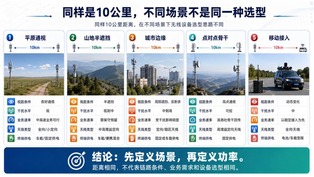
Because “10 km” is just a distance number — it doesn’t represent a complete scenario.
The same 10 km could be:
- 10 km line-of-sight over plains
- 10 km across water
- 10 km through a half-blocked valley
- 10 km on the urban edge
- 10 km fixed point-to-point
- 10 km vehicle mobile communications
- 10 km multi-channel video backhaul
These scenarios have completely different link conditions — the equipment choice can’t be the same.
Increasing distance increases path loss.
But real communication range is also affected by:
- Line-of-sight between both ends
- Operating frequency
- Antenna height
- Antenna directivity
- Channel bandwidth
- Ambient noise
- Ground reflection
- Multipath propagation
- Required throughput
- Device mobility state
So for medium-to-long-range needs, the right question order isn’t:
“Should we go straight to 20W?”
You should first ask:
- Is there line-of-sight between both ends?
- Point-to-point or point-to-multipoint?
- What business traffic needs to be carried?
- How much end-to-end throughput is required?
- Can the terminal handle the power supply and thermal load?
- Are the devices at both ends symmetric?
- What transmit power and EIRP are permitted?
In many medium/long-range links, high-gain antennas, better site positions, and more sensible channel configuration beat simply adding a few watts.
5. Antenna Height: Often, Raising the Antenna Beats Raising the Power
One of the most overlooked yet important parameters in equipment selection is antenna height.
When antenna mounting height is insufficient, you may see:
- Radio line-of-sight won’t open up
- Obvious ground blockage
- First Fresnel zone intrusion
- Severe multipath
- Increased near-ground loss
- Poor low-elevation coverage
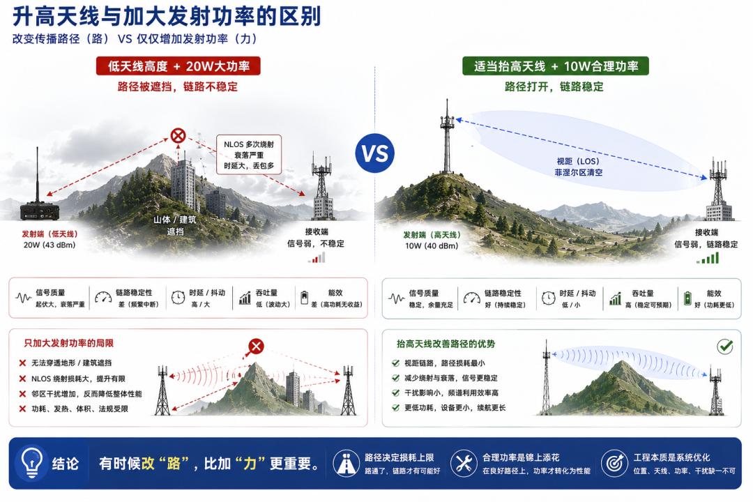
At that point, simply increasing transmit power might just:
Hit the obstacle harder.
If you raise the antenna appropriately or change its mounting position, you solve the propagation-path problem itself.
For example, a vehicle system originally uses a 10W radio with the antenna mounted low on the roof, surrounded by body panels and trees.
Even upgrading to 20W, the link may still fluctuate.
But using a mast to raise the antenna so the propagation path clears the main blockage can immediately improve link quality.
In this process, transmit power didn’t increase — yet communication got better.
This shows:
Sometimes changing the propagation path matters more than increasing transmit power.
From an engineering priority standpoint, many scenarios should first check:
- Antenna mounting height
- Antenna mounting position
- Surrounding blockage
- Fresnel zone clearance
- Antenna orientation
Then decide whether power actually needs to go up.
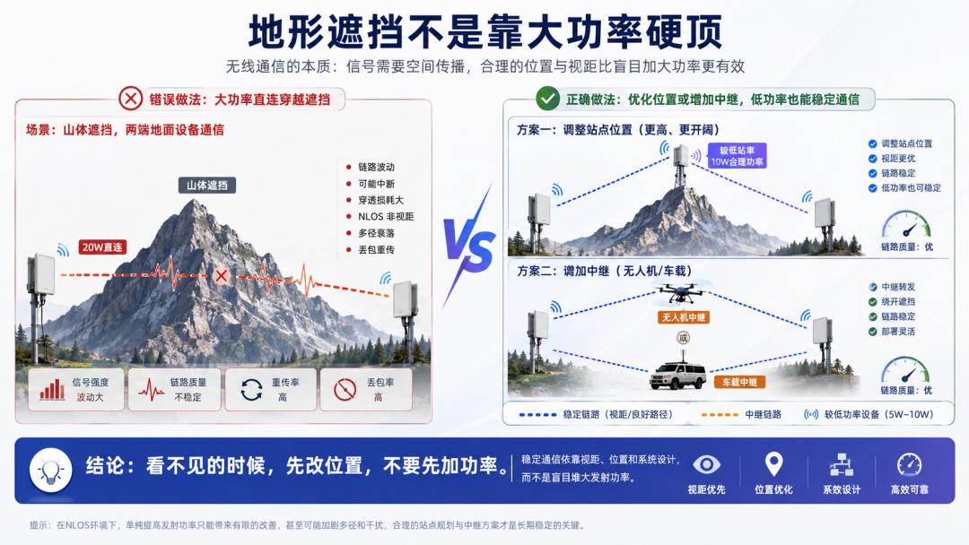
6. Terrain Blockage: A Link Blocked by a Mountain Can’t Be Fixed by Stacking Watts
Many users have this intuition when facing blockage:
“There’s an obstacle — use more power to punch through.”
But if the propagation path is clearly blocked by mountains, buildings, or dense forest, the problem usually isn’t power — the propagation mechanism has already changed.
Once a link enters non-line-of-sight or heavy-blockage state, you may see:
- Increased diffraction loss
- Severe multipath
- Deep fading
- Signal fluctuation
- Modulation level drop
- Throughput reduction
- Increased latency and jitter
- Frequent video stutter
Continuing to add power at this point usually won’t help as much as expected.
Because the real bottleneck isn’t “the source isn’t strong enough” — it’s:
The propagation path itself is unhealthy.
Against severe blockage, more sensible solutions usually include:
- Raise site height
- Adjust site position
- Route around major blockage
- Add relay nodes
- Shorten per-hop distance
- Change operating band
- Narrow channel bandwidth
- Optimize network topology
So in equipment selection, establish a basic judgment:
Blockage problems are solved primarily through position and topology — power compensation comes second.
7. Channel Bandwidth: Why Wider Bands “Eat” More Link Budget
Many people believe:
Wider bandwidth = more advanced;
Wider bandwidth = higher data rate;
Since we’re transmitting video, just open the widest bandwidth.
But wireless links aren’t better with wider bandwidth.
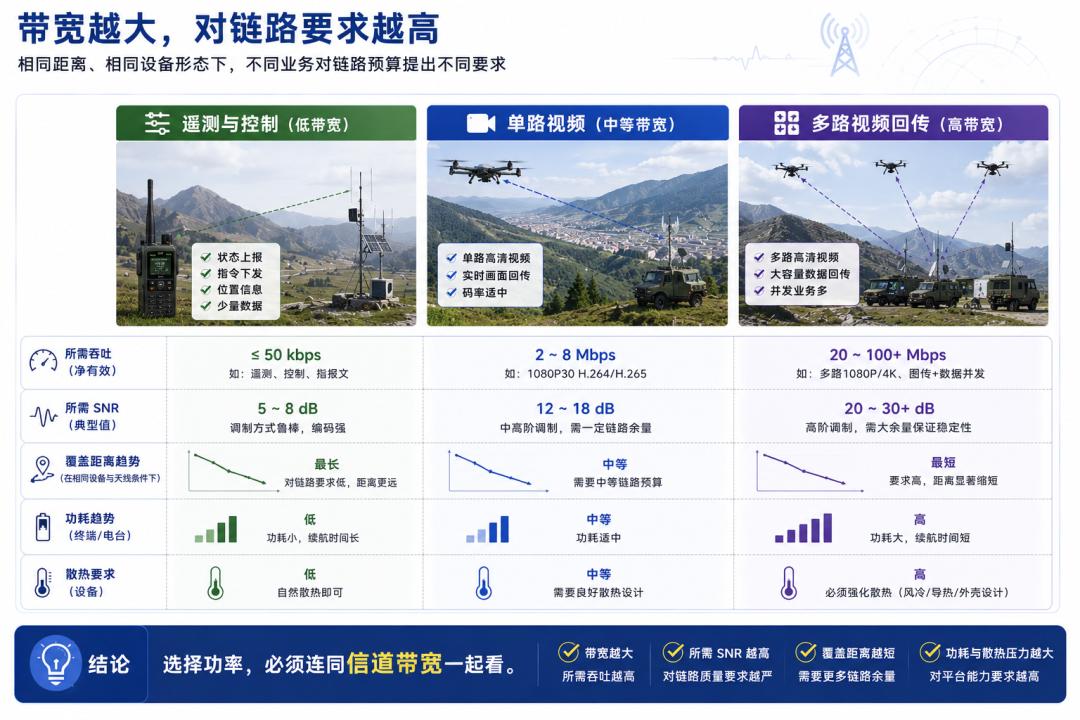
When channel bandwidth increases, the noise power the receiver picks up usually increases too.
From first principles, thermal noise power is related to bandwidth:
The wider the noise bandwidth, the higher the total received noise.
To maintain the same modulation and coding level over a wider bandwidth, the system typically needs a higher SNR.
So:
Wide bandwidth can provide higher throughput, but it also demands more from link quality.
The same radio at different bandwidths can perform very differently in coverage.
For example:
- At narrow bandwidth, 2W may already be enough
- At medium bandwidth, you may need more link margin
- With wide-bandwidth multi-channel video, even 10W may throttle due to insufficient SNR
Therefore, power selection must be considered together with channel bandwidth.
If the business is mainly:
- Low-rate telemetry
- Control signaling
- Voice
- Small status data
Blindly opening wide bandwidth only adds noise and system pressure.
If the business needs:
- Multiple HD video streams
- Large file transfer
- Data aggregation backhaul
- High-speed mobile video
You must consider together:
- Required throughput
- Required SNR
- Modulation and coding scheme
- Device processing capability
- Total power draw
- Thermal capability
- Link budget
Many projects that look like “not enough power” are actually mismatches between business goals, bandwidth configuration, and link conditions.
8. Terminal Form Factors: Dismounted, Vehicle, and Drone Can’t Be Selected With the Same Logic
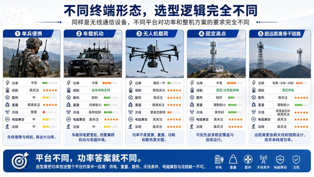
The worst mistake in equipment selection is treating every platform as the same platform.
Different terminal form factors have completely different tolerances for power, weight, battery life, and heat.
1. Dismounted Soldier Portable Terminal
For dismounted gear, what’s usually most sensitive isn’t theoretical max range, but:
- Device size
- Device weight
- Battery life
- Surface temperature
- Comfort of use
- Carrying burden
- Continuous operating time
If dismounted gear blindly chases high power, you typically get:
- Heavier devices
- Larger batteries
- Shorter battery life
- Obvious heating
- Hard to carry long-term
- Lower overall reliability
Therefore, dismounted platforms generally suit low-power, low-energy, lightweight designs — extending coverage through vehicle, high-site, or drone relays.
2. Vehicle Mobile Terminal
Vehicle platforms have far better power and thermal conditions than dismounted gear.
They can handle:
- Medium-to-high power devices
- Wider channel bandwidths
- Concurrent multi-service
- Higher duty cycles
- Multi-antenna systems
- Long continuous operation
But vehicle platforms have limits too.
You must also consider:
- Vehicle body blockage of antennas
- Isolation between antennas
- Vehicle power transient interference
- Noise from engine and motors
- Whole-vehicle EMC
- Driving attitude and vibration
- Antenna height variation
So vehicles are the typical platform for medium-high power — but still need systematic integration.
3. Drone Payload
Drone platforms are very sensitive to:
- Device weight
- Total power draw
- Heat
- Electromagnetic interference
- Antenna wind resistance
- Attitude changes
- Flight endurance
A drone’s biggest natural advantage is altitude.
Since altitude already improves radio line-of-sight, there’s no need to blindly chase high power like ground platforms.
For drones, sensible relay positioning, antenna design, MIMO performance, and channel configuration usually beat simply adding power.
4. Fixed High Site
Fixed high sites typically have:
- Relatively stable power supply
- Better thermal conditions
- Higher antenna mounting positions
- More standardized antenna systems
- More stable site environments
So fixed high sites can more easily use medium-high power equipment.
But even fixed sites need evaluation of:
- True line-of-sight
- Surrounding interference complexity
- Antenna orientation
- 24/7 operation needs
- Lightning and protection requirements
- Regulatory compliance
5. Ultra-Long-Distance Backbone Links
Backbone links are most often misunderstood as:
“Long distance, so use 20W directly.”
In reality, what matters most for backbone links is usually:
- High-gain directional antennas
- Sufficiently high sites
- Complete line-of-sight conditions
- First Fresnel zone clearance
- Precise antenna alignment
- Sensible channel bandwidth
- Low-noise receive design
- Ample fading margin
Backbone links may indeed use higher power, but what decides project success isn’t usually the extra watts — it’s whether the entire link engineering is rigorous.
9. Battery Life: High-Power Devices Often Lose on Power Supply First
Many wireless projects fail not on the link but on endurance.
When transmit power increases, total device power draw usually rises too.
And it’s not just the PA’s own consumption — it cascades:
- Power conversion losses
- Cooling system power draw
- Battery capacity requirements
- Cable cross-sections
- Connector specifications
- Power module size
- Total device weight
For battery-powered platforms, this problem is especially obvious.
Dismounted scenario
A few hundred grams extra on the device, one more battery to carry — seems minor, but in long missions it noticeably increases personnel burden.
Drone scenario
Higher comms payload power draw directly shortens flight endurance.
Reduced endurance doesn’t just mean shorter flight time — it affects:
- Effective relay time
- Safe return margin
- Mission execution windows
- Backup node scheduling
- Battery cycle count
Temporary deployment scenario
If equipment runs on battery boxes, solar, or emergency power, high-power devices significantly increase supply and maintenance pressure.
So during selection you must ask a very practical question:
Can this platform actually afford this much power?
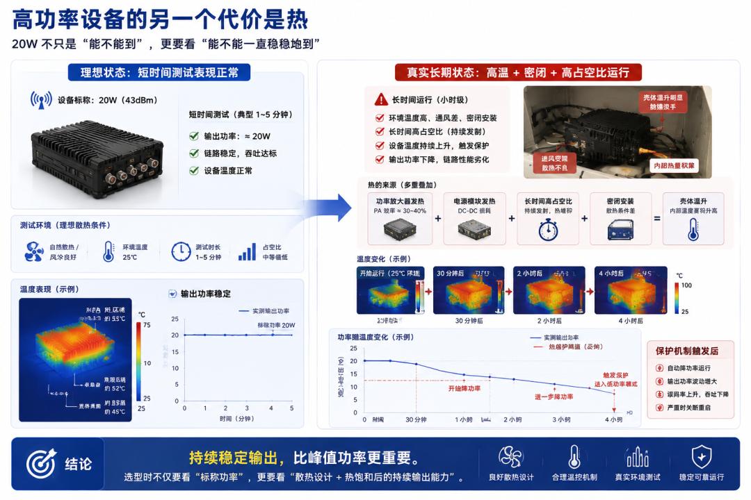
10. Thermal Management: Rated 20W Doesn’t Mean Sustained 20W Output
When power increases, heat increases.
This is very basic — yet often underestimated.
Main heat sources in wireless devices include:
- Power amplifier
- RF front-end
- Power module
- Digital baseband processor
- Video processing module
- Long high-duty-cycle operation
If thermal capability is insufficient, the device may exhibit:
- Automatic transmit power reduction
- Thermal protection
- Performance drift
- Frequency stability degradation
- Throughput reduction
- Long-run instability
- Shortened component lifetime
- Frequent alarms in hot environments
So “20W” printed on the enclosure doesn’t mean it can sustain 20W output in every environment.
Selection must also look at:
- Is 20W peak power or sustained power?
- Stable under high duty cycle?
- Does it derate in high temperature?
- Does it rely on external fans?
- How good is enclosure heat dissipation?
- Is the installation environment ventilated?
- Is there a thermal protection strategy?
For vehicle, drone, rack, and portable devices, thermal conditions are completely different.
So more important than peak power is:
Whether the device can work stably for long periods in real environments.
11. Weight, EMC, and Regulation: Why They Can Be Veto Items
Further into a project, what actually kills a solution is often not the link itself but overlooked engineering issues.
1. Device weight
Higher power usually means:
- Bigger power amplifier
- Stronger power module
- Heavier thermal structures
- Larger batteries
- Thicker cables
- Bigger chassis
These changes are especially sensitive for dismounted and drone platforms.
For drones, the increase isn’t just the device itself — it also includes mounting brackets, power conversion modules, antennas, and thermal structures.
The end result can be:
- Shorter flight endurance
- Reduced payload
- Worse wind resistance
- Insufficient safe-return margin
2. Electromagnetic compatibility
When power increases, EMC problems usually become more obvious.
High-power RF devices can affect surrounding systems, such as:
- Vehicle electronics
- Drone flight controllers
- GNSS receivers
- Electronic compasses
- Telemetry links
- Video equipment
- Other wireless terminals
They can also produce:
- Near-field self-interference
- Harmonic interference
- Out-of-band emissions
- Co-sited multi-system interference
- Insufficient antenna isolation
- Receiver blocking
So high power isn’t just “transmits farther” — it means harder system integration.
3. Regulatory limits
Wireless devices can’t transmit at whatever power you want.
Different bands, regions, and use scenarios may impose explicit requirements on:
- Transmit power cap
- Effective isotropic radiated power (EIRP)
- Operating frequency
- Channel bandwidth
- Duty cycle
- Antenna type
- Use area
- Equipment certification
- Radio station license
Sometimes the device itself can output 20W, but paired with a high-gain antenna, the system’s EIRP may exceed the limit.
So regulatory limits can’t be checked at the very end of the project.
They should be a prerequisite of equipment selection.
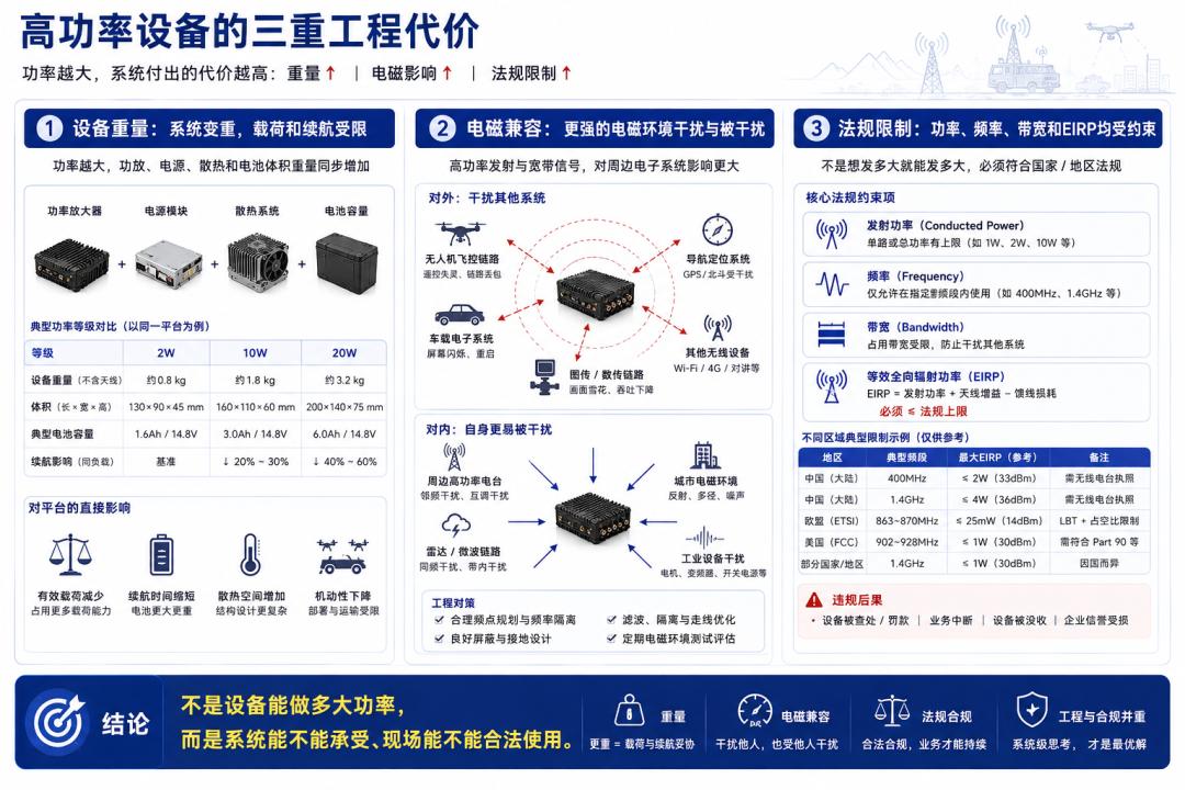
12. Five Typical Platforms: How to Combine Selection
Below are typical selection approaches for five common platforms.
Note: these are engineering directional recommendations, not universal answers detached from specific bands, distances, antennas, and business requirements.
1. Dismounted Portable: Prioritize Low Power, Light Weight, Long Endurance
- Personnel-carried
- Mobile use
- Low antenna height
- Sensitive to weight and endurance
- Business is mainly voice, control, telemetry, and light video
The core issue for dismounted gear usually isn’t chasing max theoretical range, but:
- Can it be light?
- Can it work long hours?
- Is surface temperature acceptable?
- Is it easy to operate?
- Is it reasonable to carry?
- Power tendency: 2W class or low-to-medium power first
- Antenna type: lightweight omnidirectional
- Bandwidth tendency: low-to-medium
- Power supply: swappable batteries
- Optimization focus: positioning, networking, relay capability
Don’t make dismounted terminals carry coverage tasks that belong to vehicle, high-site, or drone relays.
2. Vehicle Mobile: Medium to Medium-High Power
- Has vehicle power supply
- Relatively good thermal conditions
- Antennas can mount on roof or mast
- Can handle wider bandwidth and multi-service
- Suits mobile deployment and emergency comms
The vehicle platform’s focus is balancing performance, mobility, power, and system integration.
- Power tendency: 10W class is common
- Antenna type: roof omnidirectional, mast antennas
- Bandwidth tendency: medium to higher
- Power supply: vehicle DC
- Optimization focus: EMC, body blockage, antenna layout, power stability
Vehicles are the most common platform for medium-high power — but not simply bolting the biggest radio into a truck.
3. Drone Payload: Prioritize Low Power and Light Weight
- Weight-sensitive
- Power-sensitive
- Heat-sensitive
- EMI-sensitive
- Platform inherently has altitude advantage
- May handle both sensing and relay tasks
The drone platform’s biggest constraint usually isn’t link distance, but:
- Endurance
- Payload
- Heat
- Attitude changes
- EMC
- Antenna mounting
- Power tendency: 2W class or low-to-medium first
- Antenna type: lightweight, low wind resistance
- Bandwidth tendency: set by video or relay needs
- Power supply: onboard power or separate battery
- Optimization focus: relay position, antenna pattern, thermal design, endurance
A drone link’s advantage comes first from altitude and position — not from a bigger power amplifier.
4. Fixed High Site: Can Use Medium-High Power, But Depends on Site Engineering
- Fixed position
- High antenna mounting
- Stable power supply
- Easier thermal control
- Suits area coverage or relay backhaul
Fixed high sites can more easily handle high power, but what really determines performance is:
- Site height
- Antenna gain
- Antenna orientation
- Surrounding interference
- Long-term stability
- Lightning and protection
- Power tendency: 10W to 20W class both possible
- Antenna type: high-gain omni, sector, or directional
- Bandwidth tendency: set by coverage/backhaul needs
- Power supply: mains, solar, or backup power
- Optimization focus: site engineering, antenna layout, lightning protection, thermal, compliance
Fixed high sites can use more power — but site position and antenna system usually matter more than the wattage.
5. Ultra-Long-Distance Backbone: Full System Design, Not Just 20W
- Long transmission distance
- Mostly fixed point-to-point
- High stability and throughput requirements
- Long continuous operation
- Strict link budget requirements
Backbone links don’t just chase big power — they pursue:
- Sufficient link margin
- Stable throughput
- Low failure rate
- High interference immunity
- Long continuous operation
- Power tendency: 10W or 20W class, per link budget
- Antenna type: high-gain directional
- Bandwidth tendency: precisely configured for actual throughput
- Power supply: stable fixed supply plus backup
- Optimization focus: site LOS, Fresnel zone, antenna alignment, thermal, regulation
Backbone links truly depend on high sites, high gain, precise alignment, and complete link budgets — not just stacking watts.
13. Seven Most Common Misconceptions in Real Consultations
Misconception 1: Long distance means you must use more power
Wrong.
Distance is just one variable — LOS conditions, antenna height, antenna gain, and channel bandwidth are often more critical.
Misconception 2: Blocked by a mountain? More power will fix it
Wrong.
Obvious blockage should be solved primarily through position, height, relays, and topology.
Misconception 3: 20W is always much farther than 10W
Wrong.
Going 10W → 20W adds only 3 dB of link budget — real improvement may be marginal.
Misconception 4: Only look at transmit power, ignore receive capability
Wrong.
Wireless comms is usually bidirectional. Big power on one side doesn’t guarantee the reverse link works.
Misconception 5: Wider bandwidth is more advanced
Wrong.
Wider bandwidth means more noise and higher SNR/link-margin demands.
Misconception 6: Drones should also use high-power equipment
Wrong.
Drones are more sensitive to weight, power draw, heat, EMC, and endurance.
Misconception 7: Regulatory limits can be checked last
Wrong.
A solution that violates frequency, power, bandwidth, or EIRP requirements can’t be deployed no matter how good the tech looks.
14. What Should a Professional Selection Process Look Like?
A sensible wireless equipment selection process shouldn’t start with “how many watts.”
Step 1: Define the business
What needs to be carried?
- Voice
- Telemetry
- Control
- Single video stream
- Multiple HD streams
- Files
- Aggregation backhaul
Step 2: Define performance targets
What metrics must be met?
- Communication distance
- End-to-end throughput
- Latency
- Jitter
- Packet loss rate
- Concurrent stream count
- Continuous operating time
Step 3: Define the use scenario
Where does the equipment work?
- Plains
- Mountains
- Forest
- Urban
- Water
- Vehicle
- Dismounted
- Drone
- Fixed high site
Step 4: Analyze the terminal form factor
What can the platform handle?
- Power supply capability
- Battery capacity
- Weight
- Thermal conditions
- Mounting space
- EMC environment
Step 5: Analyze propagation conditions
Check:
- Line-of-sight
- Antenna height
- Terrain blockage
- First Fresnel zone
- Operating frequency
- Interference level
Step 6: Determine bandwidth and service configuration
Choose based on business needs:
- Channel bandwidth
- Modulation and coding
- Video bitrate
- QoS
- Multi-stream concurrency strategy
Step 7: Complete the link budget
Calculate:
- Transmit power
- Antenna gain
- Path loss
- Other losses
- Received level
- Receiver sensitivity
- Link margin
Step 8: Finally determine the power level
Only after all the above can you judge:
- Is 2W already enough?
- Is 10W more balanced?
- Is 20W truly necessary?
- Is the added power worth its cost?
That’s the sensible equipment selection logic.
Conclusion: Radio Selection Isn’t “Pick the Biggest” — It’s “Pick the Right One”
2W, 10W, and 20W look like simple numbers.
But in real engineering, behind them lies a whole set of system trade-offs.
Higher power may bring:
- More link margin
- Stronger coverage
- More fading headroom
But it may also bring:
- Higher power draw
- Shorter endurance
- More heat
- Heavier devices
- More complex EMC
- Harder system integration
- Stricter regulatory limits
So the truly professional selection approach isn’t to ask:
“Which device has the most power?”
It’s to ask:
“Which device is the most balanced, most reliable, and most compliant for this business, this platform, and this scenario?”
If we compress the whole article into one sentence:
Radios aren’t better when bigger. The best selection finds the right balance point among link, business, platform, and engineering constraints.
At Aomway, power selection is exactly this kind of engineering trade-off. Our FPV video transmitters, data links, and antennas are designed around the full link budget — antenna gain, bandwidth, thermal envelope, and regulatory compliance — not just raw wattage. Whether you’re flying a drone with a 2W payload or building a vehicle-based relay with a 20W backbone, the principles in this guide are the ones we apply in every product we ship. Questions about link budgets, antenna selection, or our FPV and telemetry solutions? Contact us at [email protected].
Frequently Asked Questions
1. If 10W → 20W is only +3 dB, why do some manufacturers advertise “double the range”?
Marketing “double range” claims usually rely on ideal free-space conditions or misleading test setups. In free space, +3 dB does extend range by roughly 41% (because path loss grows with the square of distance, and 10^(3/20) ≈ 1.41). Real-world links are rarely free-space: obstacles, Fresnel zone intrusion, multipath, and noise dominate. In a blocked or noisy environment, +3 dB can be completely swallowed — the practical gain may be near zero. Always ask for link-budget calculations for your actual geometry rather than trusting range marketing. The honest engineering answer: 20W buys margin, not double range.
2. Can I use one 20W radio at a fixed high site to talk to multiple dismounted 2W terminals?
Yes, but you must think bidirectionally. The high site can easily reach the dismounted terminals (20W downlink), but each dismounted terminal only has 2W uplink. If the link budget for the reverse path is insufficient — due to distance, the terminal’s low antenna height, or obstruction — the dismounted users will hear the base fine but their transmissions won’t get back. This asymmetry is a classic failure in point-to-multipoint networks. Fixes: raise the dismounted terminal’s antenna, use a relay, reduce bandwidth on the uplink, or increase the terminal’s power class if the platform allows. Always verify both directions of the link, not just the high-power side.
3. Does choosing a narrower channel bandwidth always improve range?
Generally yes — narrower bandwidth reduces the noise floor (thermal noise power scales with bandwidth), improving SNR for the same received signal, which allows lower modulation orders or better coding gains, effectively extending usable range. But there’s a trade-off: narrower bandwidth caps the maximum throughput. For voice, control, and low-rate telemetry, narrow bandwidth (e.g., 25 kHz to 200 kHz) is ideal. For HD video or data aggregation, you need wider channels — and then you must pay for it with higher power, better antennas, or shorter hops. The right answer is to match bandwidth to the business throughput requirement, then let the link budget decide the rest.
4. For drone video links, is a 2W transmitter enough for 5 km?
It can be, under the right conditions. A drone’s altitude provides excellent line-of-sight — often the single biggest win in the link budget. At 2W (33 dBm) with a decent antenna pair and a modest bandwidth, 5 km LOS links are routinely achievable at 2.4/5.8 GHz in clear conditions. What kills drone links is usually: (a) antenna pattern and polarization mismatch during banking maneuvers, (b) multipath over water or near structures, (c) interference from other 5.8 GHz users, and (d) the receiver’s sensitivity and dynamic range. Before increasing power (which costs endurance and weight), optimize antenna selection, diversity, and frequency planning. If interference is the issue, more power can actually make things worse.
5. How do I verify whether a “20W” radio can sustain 20W in my deployment?
Check the datasheet’s fine print and test in your real environment: (1) Look for peak vs. average/continuous power ratings — many radios quote peak. (2) Check duty-cycle ratings: can it do 100% duty cycle at 20W, or only 50%? (3) Run a thermal soak test: operate at maximum power in your ambient temperature (especially if it’s hot or the device is enclosed) for at least 30-60 minutes and measure whether output power, frequency error, and throughput degrade. (4) Check the thermal protection behavior — does it derate gracefully or drop the link? (5) For vehicle/drone installs, verify airflow and consider active cooling. A radio that thermally throttles mid-mission isn’t really a 20W radio for your use case.

Pingback: RF Transmitter Upgrade: Doherty PA, DPD & RF-DAC (2026) – AOMWAY