
Key Takeaways
- A gyro alone drifts: bias integrated over time walks the heading off by more than ten degrees per minute.
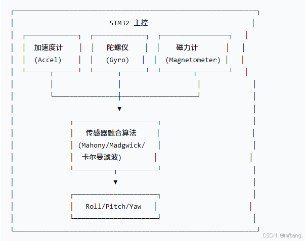
- The fix is a 9-axis build on an STM32F4, where accelerometer, gyroscope and magnetometer cover for each other.
- Magnetometer calibration runs in two steps: 200 sampled points to strip hard-iron offsets by axis extremes, then a common three-axis scale for soft-iron distortion.
- Fusion uses the Mahony complementary filter, which turns three sensor streams into a quaternion with very little compute and corrects gyro bias in real time.
- Measured on the bench: static attitude wobble stays inside ±0.5°, integrated drift falls from over ten degrees per minute to under 1°, and dynamic sway shows about 20 ms of latency.
Attitude estimation looks like a solved problem until a gyro is left running on its own. This build note from Aomway walks through a 9-axis STM32F4 setup that pairs a magnetometer with a MEMS-IMU, cleans the magnetometer data properly, and fuses everything with a Mahony filter so the output stays usable for drones and mobile robots.
Why a Gyro Alone Cannot Hold Attitude
A gyroscope answers one question very well: how fast is each axis rotating right now. It responds instantly, it is not confused by vibration the way an accelerometer is, and it needs no external reference. That is why almost every flight controller trusts it for short-term rate control.
The problem is that attitude is not measured, it is integrated. Every reading carries a small bias, and integrating a small bias produces a ramp. Even a modest zero-rate offset accumulates into a heading that visibly rotates away from reality within a minute of sitting still. On a drone, that is a slow yaw drift that no amount of PID tuning can remove.
The accelerometer can anchor roll and pitch because gravity gives it an absolute reference, and the magnetometer can anchor yaw because the earth’s magnetic field gives it a horizontal direction. Both are noisy and both are corrupted by motion — which is exactly why they are used to correct the gyro rather than to replace it.
The 9-Axis Rig
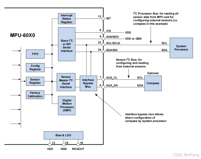
The hardware here is deliberately minimal: an STM32F4 with an accelerometer, a gyroscope and a magnetometer on the same bus. Three sensors, three failure modes, one filter.

| Sensor | What it anchors | Main weakness |
|---|---|---|
| Gyroscope | Fast dynamic response, short-term attitude | Bias integrates into unbounded drift |
| Accelerometer | Roll and pitch via the gravity vector | Confused by linear acceleration and vibration |
| Magnetometer | Yaw via the earth’s magnetic field | Easily bent by nearby magnetic material |
The Magnetometer Needs a Bath First
Raw magnetometer readings on a real board are almost never usable as-is. Solder, shielding cans, battery cells, steel screws and the PCB traces themselves all sit within centimetres of the sensor and distort the field it measures. Feed that straight into a fusion filter and the yaw estimate inherits every bit of the distortion.
The calibration used here is the standard two-step routine. The device is rotated through as many orientations as possible — in this case roughly 200 sampled points collected by walking around the room — so that each axis sweeps through its full range.
Step 1: hard-iron offset
Hard-iron interference is a constant magnetic field added by permanently magnetised material. It shifts the whole measurement cloud away from the origin, and it is removed simply by finding each axis’ minimum and maximum and subtracting the midpoint:
offset_x = (max_x + min_x) / 2
offset_y = (max_y + min_y) / 2
offset_z = (max_z + min_z) / 2

corrected = raw - offset
Step 2: soft-iron scaling
Soft-iron distortion is not a shift but a deformation: the field is stretched differently along different axes, so a sphere of true field vectors arrives as an ellipsoid. A single common scale factor applied to all three axes, derived from the same extremes, pulls the ellipsoid back toward a sphere. It is a coarse correction rather than a full 3×3 matrix fit, but it costs almost nothing and removes the bulk of the error — which is why it is the practical choice on a microcontroller.
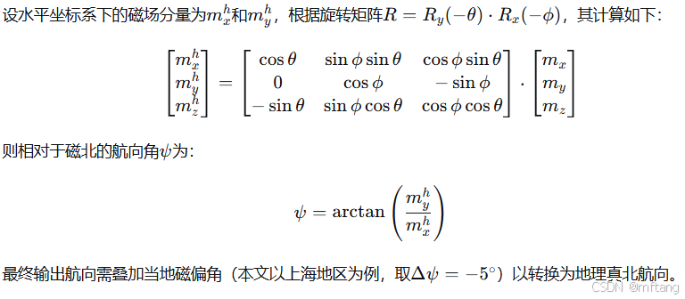
Once the field has been cleaned, the heading follows from the horizontal components of the corrected vector, rotated into the level frame and corrected for local magnetic declination:
Mahony Filter: Cheap, Real-Time, Good Enough
With the magnetometer cleaned up, the three streams are fused into a quaternion using the Mahony complementary filter. The structure is simple and that is the point.
- The gyro is integrated to propagate the quaternion forward at the full loop rate.
- The accelerometer measures gravity and the magnetometer measures the field direction. Both give a second, absolute estimate of where “up” and “north” should be.
- The difference between the predicted and measured reference vectors becomes an error signal.
- That error drives a proportional-integral correction term which is fed straight back into the gyro rate — this is what cancels the bias instead of merely masking it.
Two properties make it a good fit for embedded attitude work. It is a complementary structure, so tuning is a matter of one gain balancing trust in the gyro against trust in the reference vectors, not a covariance matrix. And because the correction is applied at the rate level, the gyro bias is compensated continuously rather than estimated offline in a separate procedure.
The trade-off is honesty about what it is not: Mahony is not an EKF. It does not model process noise, it does not carry a covariance, and it will not gracefully arbitrate between conflicting sources when the accelerometer is loaded by aggressive manoeuvres. For attitude-only output on a vehicle that spends most of its time near level, that is a fair trade.
Measured Results
The numbers below are the author’s bench measurements on this build, not a comparison across filters.
| Condition | Gyro integration only | With Mahony fusion |
|---|---|---|
| Static, attitude wobble | drifts continuously | within ±0.5° |
| Drift over one minute | more than ten degrees | under 1° |
| Latency under dynamic sway | — | about 20 ms |
Twenty milliseconds of latency under dynamic sway is the figure that matters for a flight application. It is fast enough that the attitude estimate can sit inside a control loop for a drone or a ground robot, which is what the author concludes: this is directly usable, not just a bench demo.
Where This Fits in a UAV Stack
Attitude estimation of this kind is the layer underneath everything else. A flight controller’s rate loop needs a trustworthy attitude before it can stabilise anything, and a gimbal, a video link with a directional antenna, or a navigation stack following GPS waypoints all consume the same estimate. Getting a clean quaternion out of three cheap MEMS sensors is often the difference between a platform that holds heading in a hover and one that slowly rotates on the spot.
Two practical notes from the build. First, calibrate the magnetometer in the environment it will be used in — a calibration done on a workbench with a power supply nearby can be worse than useless. Second, verify the fusion output against an independent reference before trusting it, because a filter with the wrong gains can look perfectly smooth while being steadily wrong.
FAQ
Why not just raise the gyro sampling rate instead of fusing sensors?
Sampling faster does not help a bias. A zero-rate offset integrated at any rate still produces a linear ramp. Faster sampling improves the resolution of the ramp, not its slope, so the drift remains until an absolute reference corrects it.
How many calibration points does the magnetometer need?
This build used about 200 points collected by rotating the device through as many orientations as possible. The requirement is coverage, not count: every axis needs to reach both its minimum and its maximum, or the extreme-based offset and scale will be biased.
Is a single scale factor enough for soft-iron correction?
It removes the bulk of the distortion for very little compute, which is why it is used here. A full ellipsoid fit with a 3×3 matrix is more accurate and is worth the extra math when yaw accuracy is the limiting error source.
What is the difference between Mahony and Madgwick?
Both are complementary filters driven by the same reference vectors. Mahony applies the correction as a proportional-integral term on the gyro rate, while Madgwick uses a gradient-descent step on the quaternion. Mahony tends to be cheaper and easier to tune; both avoid the cost of a full EKF.
When should I move up to an EKF?
When you need more than attitude — position, velocity, and fusion with GPS, barometer or optical flow — or when the platform manoeuvres hard enough that the accelerometer’s gravity assumption breaks down. At that point covariance modelling starts to pay for itself.
About Aomway
Aomway has spent more than a decade building wireless video, datalink and flight-control hardware for FPV and industrial UAV platforms. Explore the Aomway product line for video transmitters, antennas, fiber-optic links and onboard electronics that hold up in real flight conditions.
Have questions about this article? Feel free to contact us at [email protected] — we’re happy to help!