

Control System Design for Small Reusable Rockets
Building on the previously established trajectory design and guidance law, this chapter focuses on the design and construction of the flight control system for a small reusable rocket. The control system design primarily consists of two parts: control allocation and flight control law design. The control allocation module forms actuator commands based on required control moments, distributing expected control moments across气动 control surfaces, Thrust Vector Control (TVC), and the Reaction Control System (RCS). The flight control law ensures attitude stability and tracking, generating the required control moments. This chapter linearizes the full nonlinear dynamics model via small-disturbance equations and designs channel-specific control law parameters for different flight phases.
1. Control Allocation Design
This study uses two engines with bidirectional gimbaling. The engine installation radius is r, with a 135-degree angled layout. The engine distribution diagram:
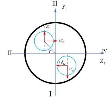
Figure 1: Engine gimbal angle relationship
Converting the four-channel gimbal angles to three-channel:
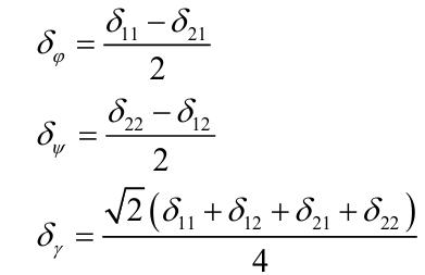
The combined gimbal angle formula:
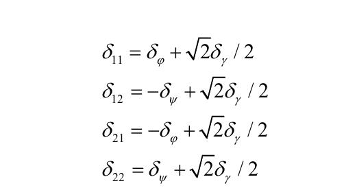
1.1 Control Forces and Moments
For the powered phase, control authority analysis uses engine gimbaling. The active-phase engine thrust and control force terms can be expressed together as:
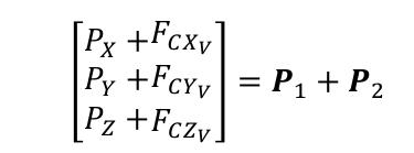
Where:
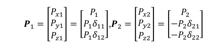
Since both engines produce equal thrust:

In the body frame, engine thrust also produces a thrust moment:
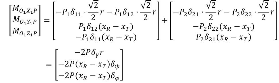
Where:
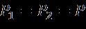
r is the engine installation radius, xR is the engine hinge point position (measured from the nose), and xT is the rocket center of mass position.
1.2 Engine Gimbal Inertia Forces and Moments
While generating thrust, the engine also produces gimbal inertia forces that disturb the rocket’s flight.
Let mR denote the mass of a single engine, lR and JR denote the distance from the engine center of mass to the hinge axis and the moment of inertia about the hinge axis, respectively. The engine’s gimbal motion can be modeled as a concentrated mass pendulum of mass mR and length lR. The force exerted by the main engine gimbal on the rocket center of mass:
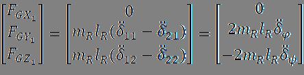
Projections onto the semi-velocity coordinate system axes are obtained through the coordinate transformation matrix:
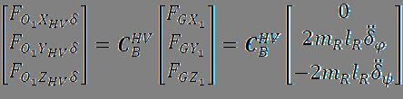
Where JR is the engine moment of inertia about the rotation axis, mR is the engine gimbal mass, and lR is the distance from the engine center of mass to the gimbal axis.
2. Flight Control Law Design
2.1 Linearized Model for the Powered Phase
The small reusable rocket’s powered phase is described by differential equations for pitch, yaw, and roll angles for center-of-mass motion, and angular rate differential equations for attitude motion.
Before establishing the linearized model, the following assumptions are made:
① Ignore gravity effects; consider only aerodynamic forces and thrust;
② Ignore actuator nonlinearity; use an equivalent first-order lag element;
③ Ignore rate gyroscope and accelerometer dynamics;
④ The rocket’s principal inertia axes coincide with body axes; ignore products of inertia.
Since the full nonlinear model is a set of high-dimensional, nonlinear, variable-coefficient differential and algebraic equations, it cannot be directly used for stability analysis or attitude control design. Based on the motion characteristics and modeling assumptions, the nonlinear model must be linearized via small-disturbance perturbation, separating rocket motion into three independent channels.
Without external disturbances, the rocket generally flies along the standard trajectory plane (pitch plane) during ascent. Yaw and roll channel standard trajectory parameters are zero, as are propellant sloshing and elastic vibration quantities. Therefore:


Under the small-disturbance assumption, attitude angles are small quantities. The coordinate transformation matrix Euler angle relationship linearizes to:

The Euler kinematic equations linearize to:

The rocket center-of-mass apparent acceleration simplifies to:
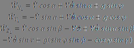
Linearizing:


Based on the above small-disturbance assumptions, the pitch channel center-of-mass motion equations simplify to:

Similarly, the yaw channel center-of-mass equations and attitude rotation equations can be linearized, ultimately yielding the small-deviation incremental attitude dynamics model. Separating by channel, the pitch channel includes the following equations in addition to center-of-mass motion:
Translational dynamics:

Pitch angle relationship:
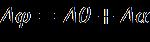
Translational dynamics:

Rotational dynamics about center of mass:

Angle relationship:
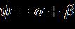
Roll channel small-deviation attitude dynamics:

The coefficient formulas in the above equations:
(1) Center-of-mass motion equation coefficients:
Pitch channel:


Yaw channel:


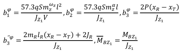
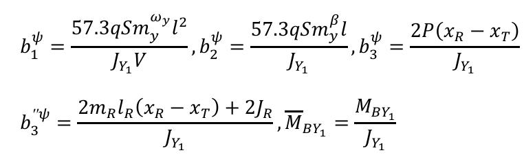
(2) Rotation equation coefficients about center of mass:
Pitch channel:
Yaw channel:
Roll channel:

2.2 Rigid Body Controller Design at Powered-Phase Feature Points
Using the small-disturbance linearized model, pitch, yaw, and roll controllers are designed separately.
(1) Pitch Channel Rigid Body Controller
From the linearized equations, the pitch channel small-disturbance linearized equations (ignoring disturbance forces and moments) are:
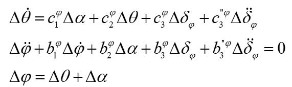
Taking the Laplace transform:
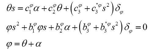
Let:

Yielding:
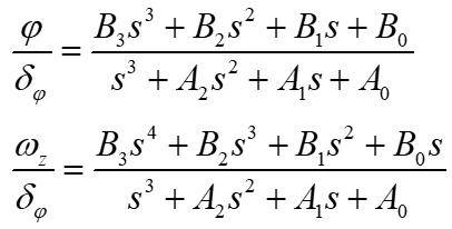
Since the engine moment of inertia is small for a small reusable launch vehicle, the engine gimbal inertia forces and moments can generally be neglected, simplifying the transfer function to:
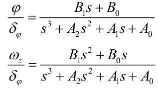
The pitch channel control system structure:
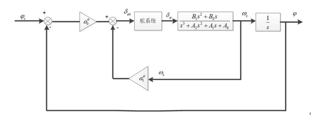
Ascent-phase pitch channel control system structure
During vertical takeoff and landing, the pitch channel control parameters are set to:
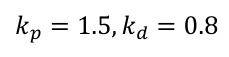
Using the 30-second feature point, the pitch channel step response and Bode plot:
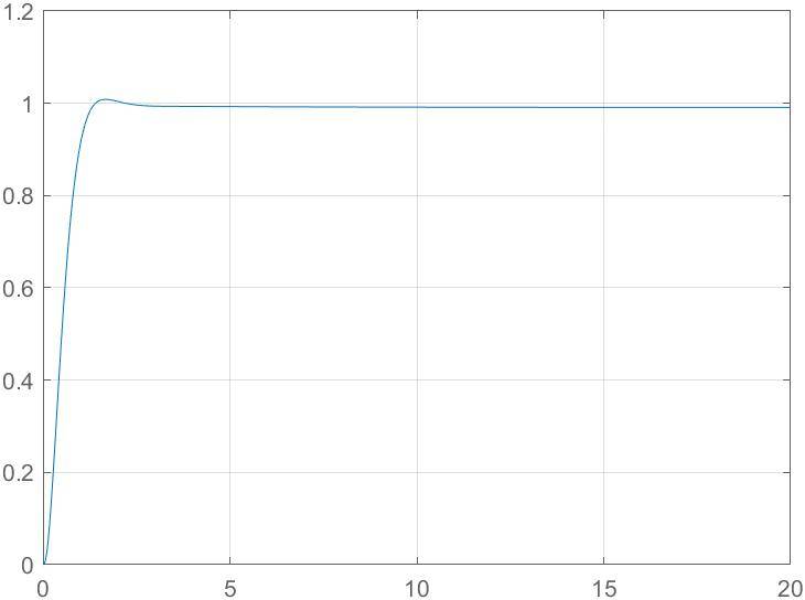
Pitch channel 30s step response
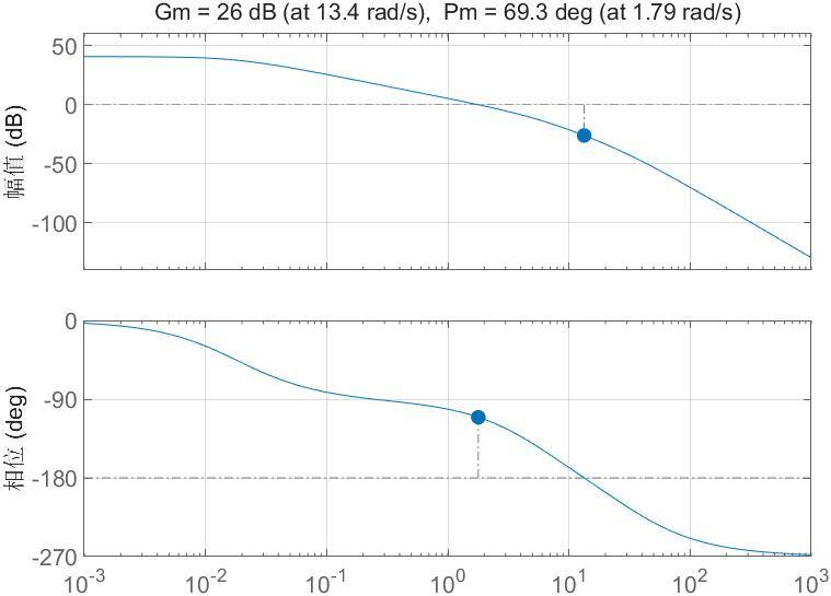
Pitch channel 30s Bode plot
The figures show fast step response with small overshoot, meeting dynamic performance requirements. The gain margin Gm is 26 dB and phase margin Pm is 69° — both meet requirements.
(2) Yaw Channel Single-Point Controller
The rocket is axisymmetric, so only pitch channel parameters need to be designed. The yaw channel control parameters are identical to the pitch channel.
(3) Roll Channel Single-Point Controller
From the linearized model, the roll channel can be expressed as:
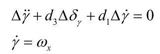
Let:
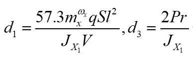
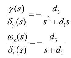
The Laplace transform yields the transfer function:
Roll channel control system structure:
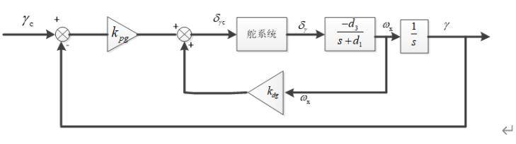
Ascent-phase roll channel control system structure
During vertical takeoff and landing, the yaw channel control parameters are set to:

Using the 30-second feature point, the roll channel step response and Bode plot:
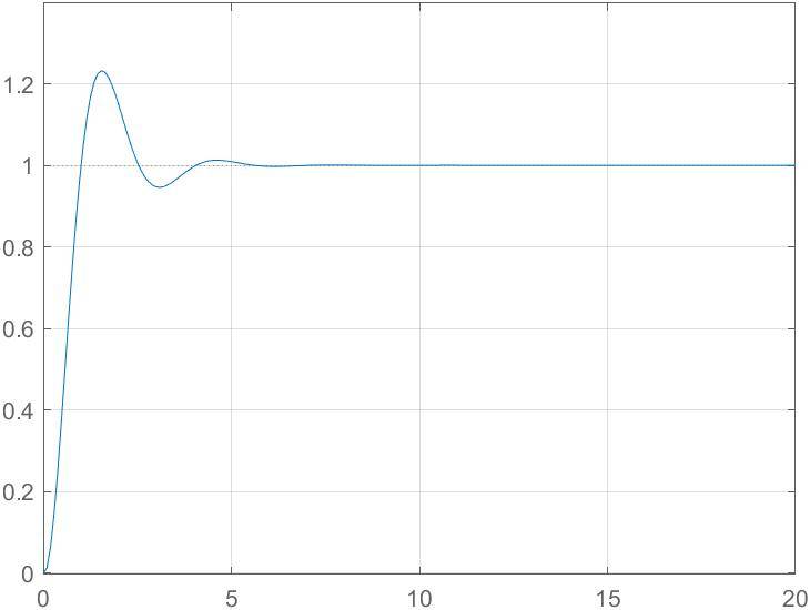
Roll channel 30s step response
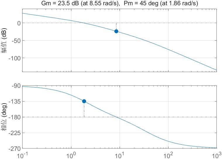
Roll channel 30s Bode plot
The roll channel responds slower than pitch and yaw, with approximately 20% overshoot, still meeting dynamic performance requirements. The gain margin is 23.5 dB and phase margin Pm is 45° — both meet requirements, with strong stability.
3. Simulation and Validation
After adding actuator and three-channel control law modules to the guidance system, the small reusable rocket’s control system can be simulated.
3.1 Simulation Results Analysis
With the control loop built, the rocket vertical takeoff and landing simulation yields range-altitude and pitch angle curves:
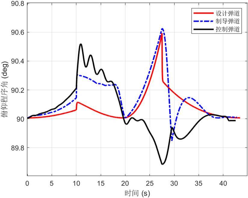
Pitch angle simulation curve
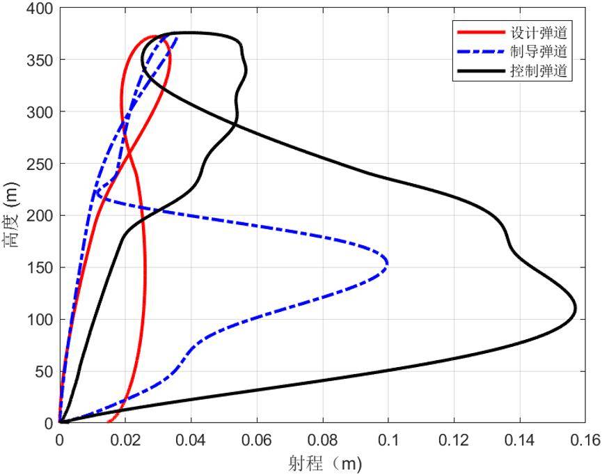
Range-altitude simulation curve
With the control loop added, the program angle and horizontal range disturbances increase slightly but remain at a low level — consistent with vertical takeoff and landing requirements.
3.2 Monte Carlo Shooting Results
Normally distributed errors are added to aerodynamic and structural coefficients:
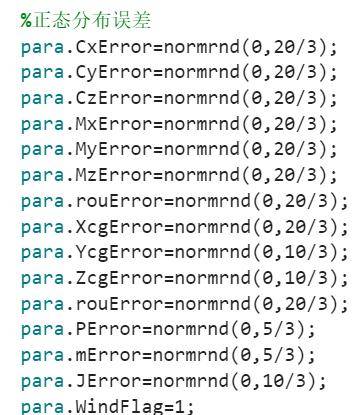
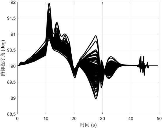
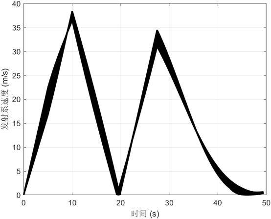
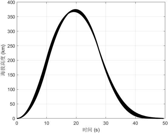
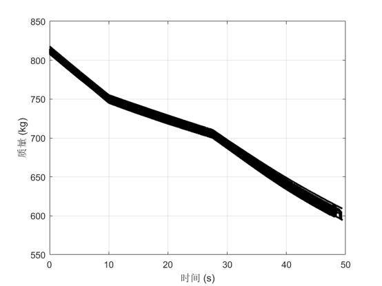
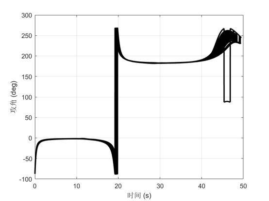
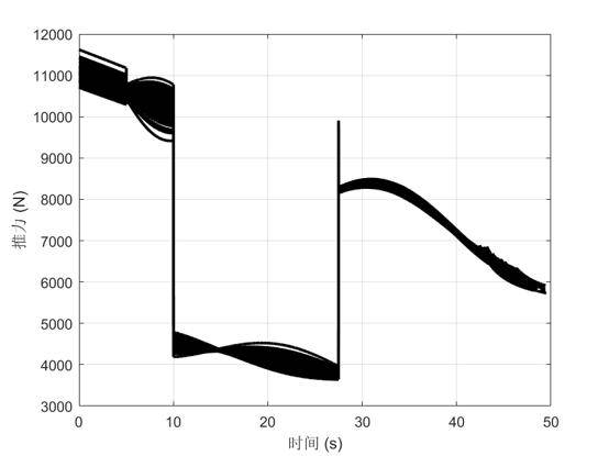
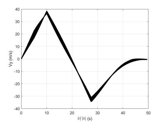
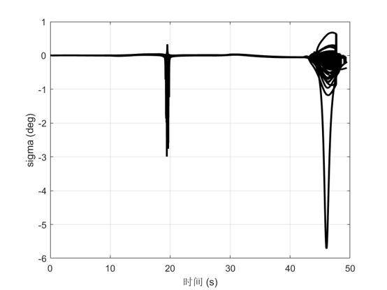
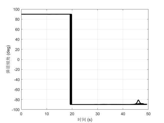
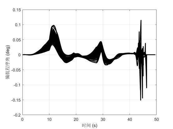
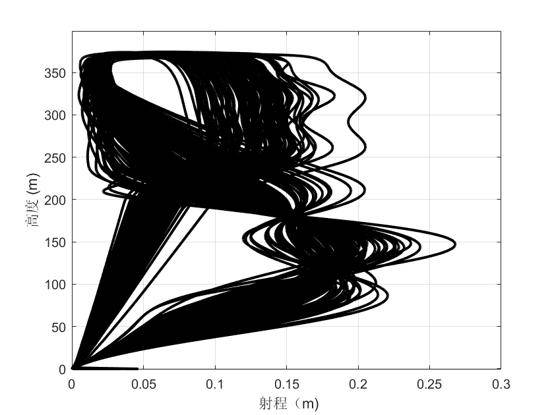
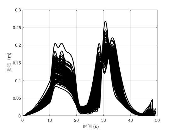
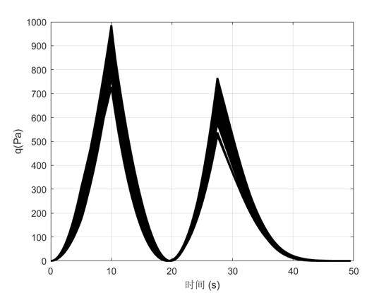
A 100-run Monte Carlo shooting analysis validates the system’s disturbance rejection under random errors:
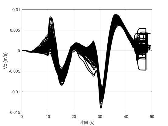
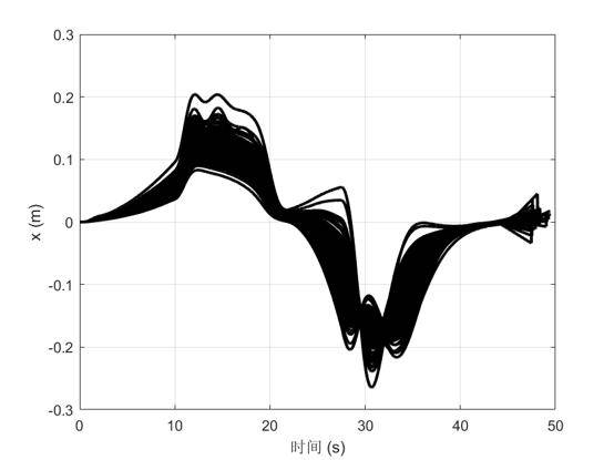
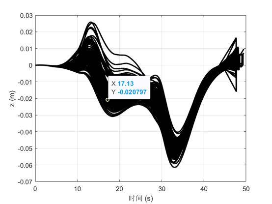
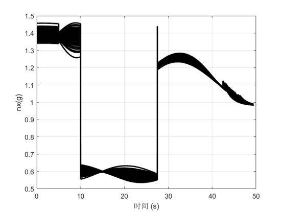
Swipe to view more
With coefficient biases added, the program angle and horizontal range disturbances increase, but the pitch program angle remains near 90°, and horizontal error during flight stays within 0.3 m — the disturbance rejection capability meets mission requirements.
For questions about reusable rocket control systems, thrust vector control allocation, or small-disturbance linearization methods, feel free to contact Aomway at [email protected].
