1. Hardware Overview: Inside the Vampire Drone
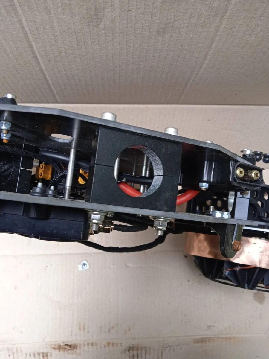
Hardware photos. The Vampire drone’s Power Distribution Board (PDB) and high-power DC-DC Buck Module are responsible for the entire aircraft’s power conversion, voltage regulation, and supplying power to each unit. The obvious gray blocks on the board (labeled 3R3, 220, etc.) and the round coil wrapped with thick copper wire are power inductors. 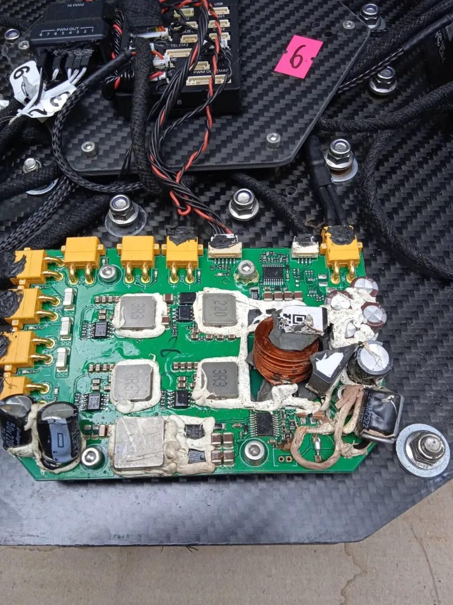
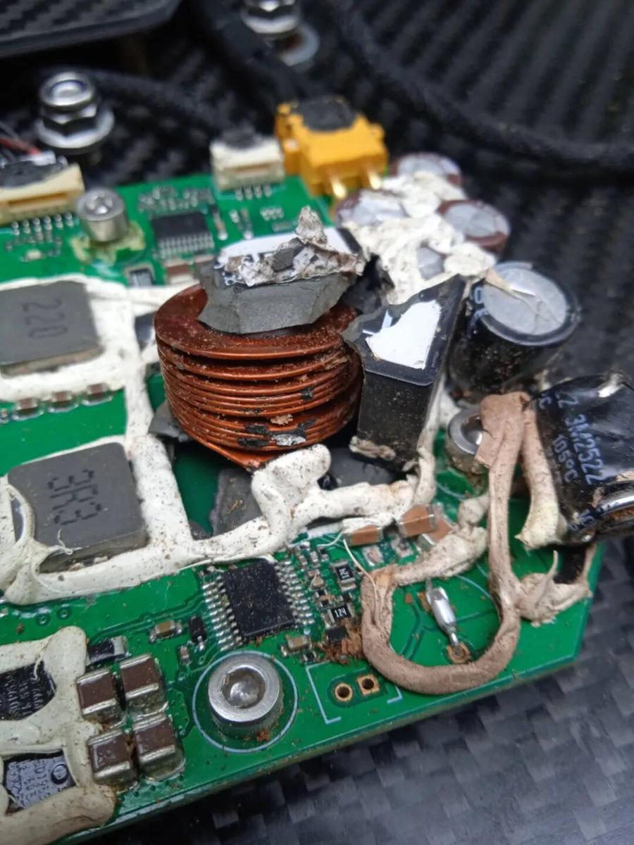
 Close-up of detailed wiring and routing (exploded power inductor), with black-wrapped power cables on the right.
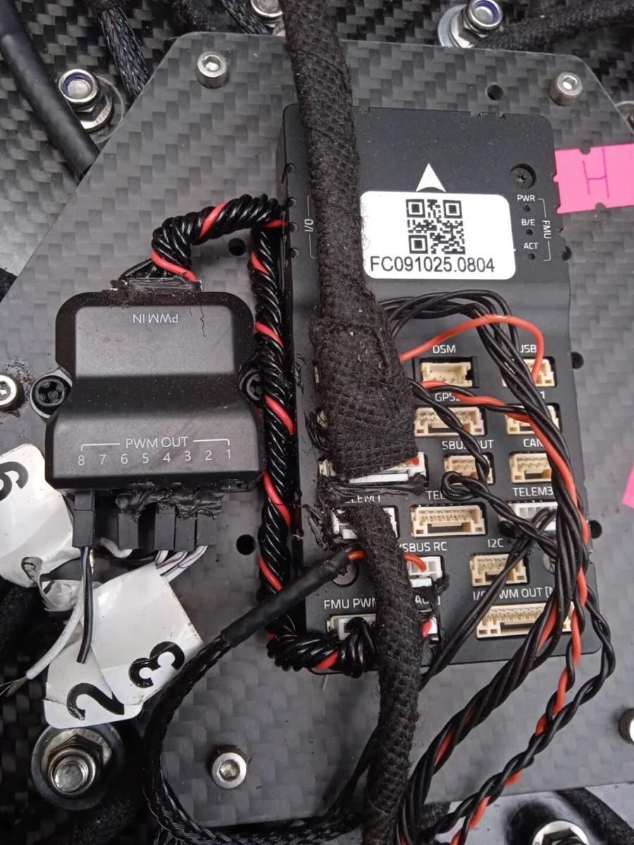
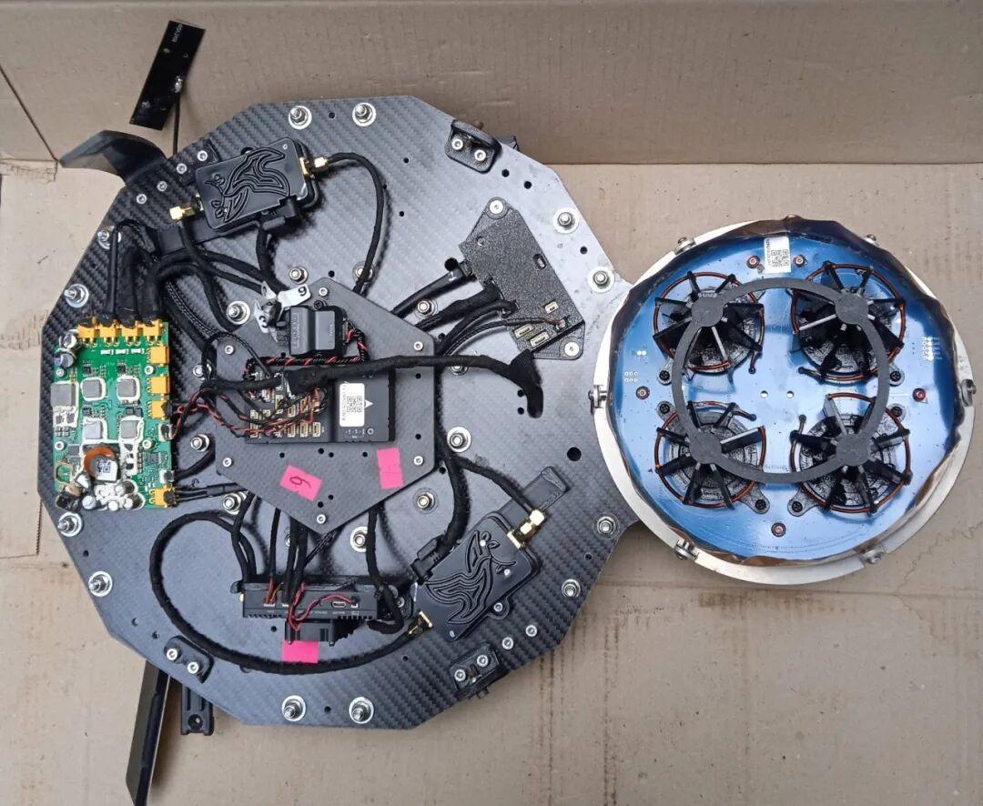
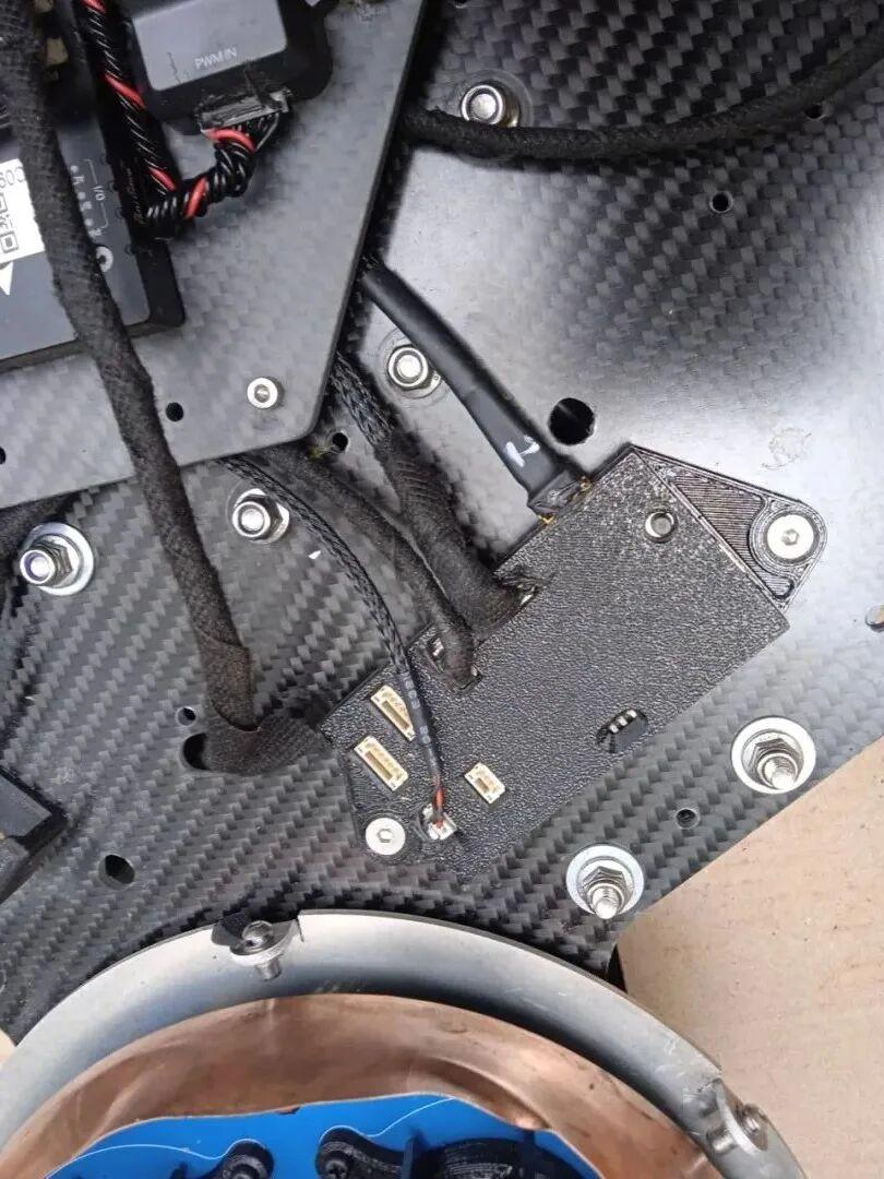 Communication interface — this is actually the drone’s “brain”: open-source flight controller system (Flight Controller) and its companion signal expansion module. It integrates a wide range of dedicated interfaces: GPS, TELEM 1 / TELEM 3 (telemetry data links), CAN, SBUS RC / DSM (RC receiver), I2C, USB-C, FMU PWM / I/O PWM.
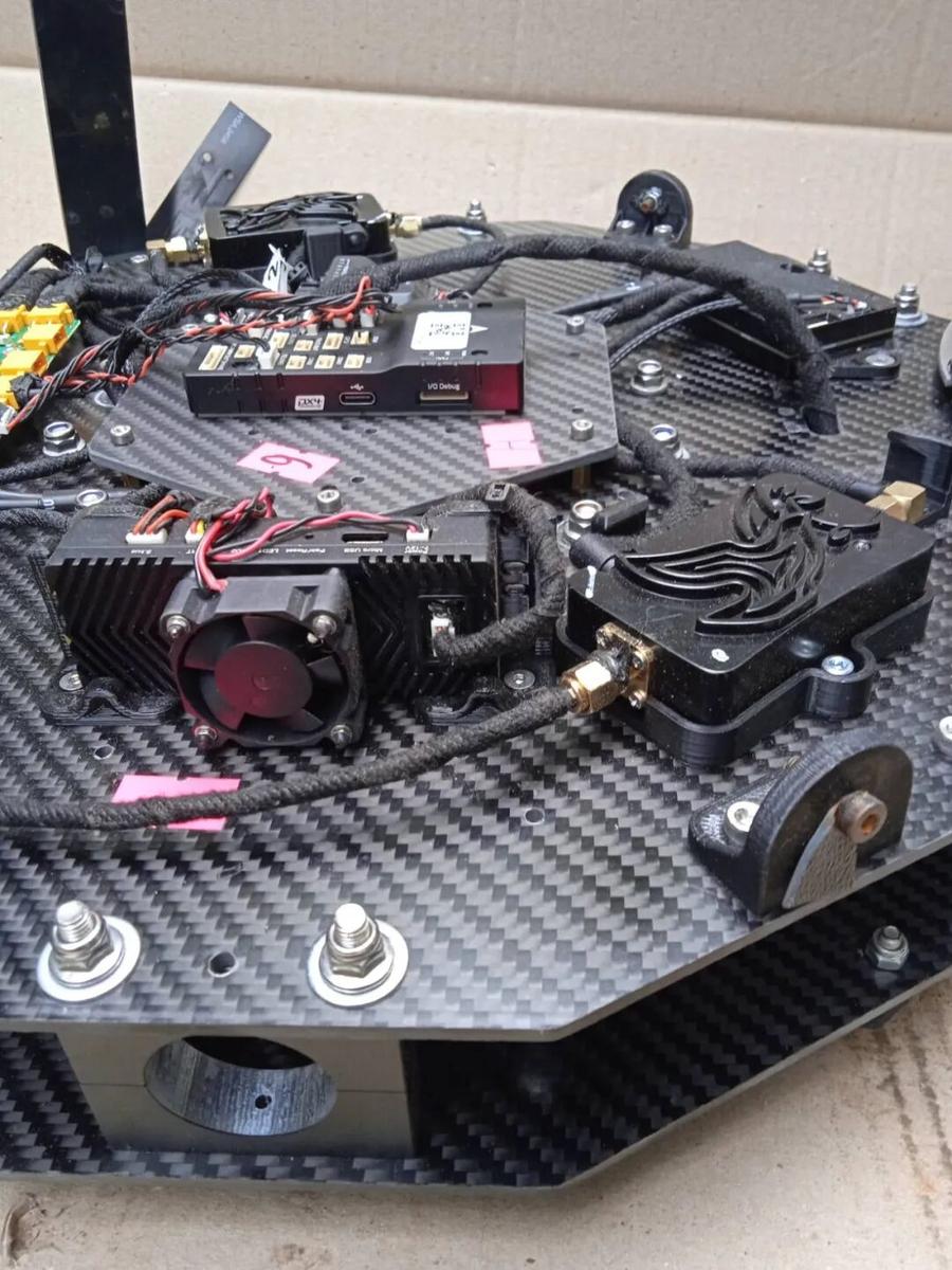
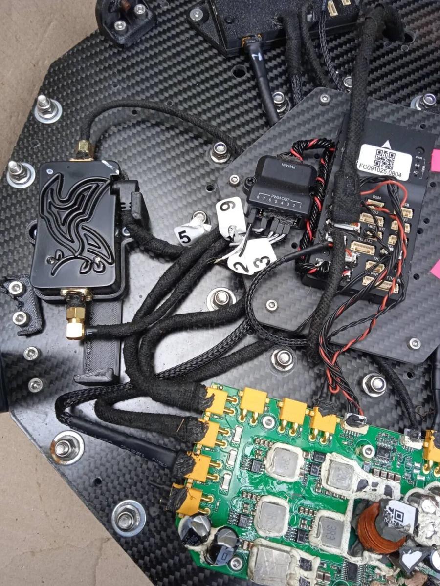
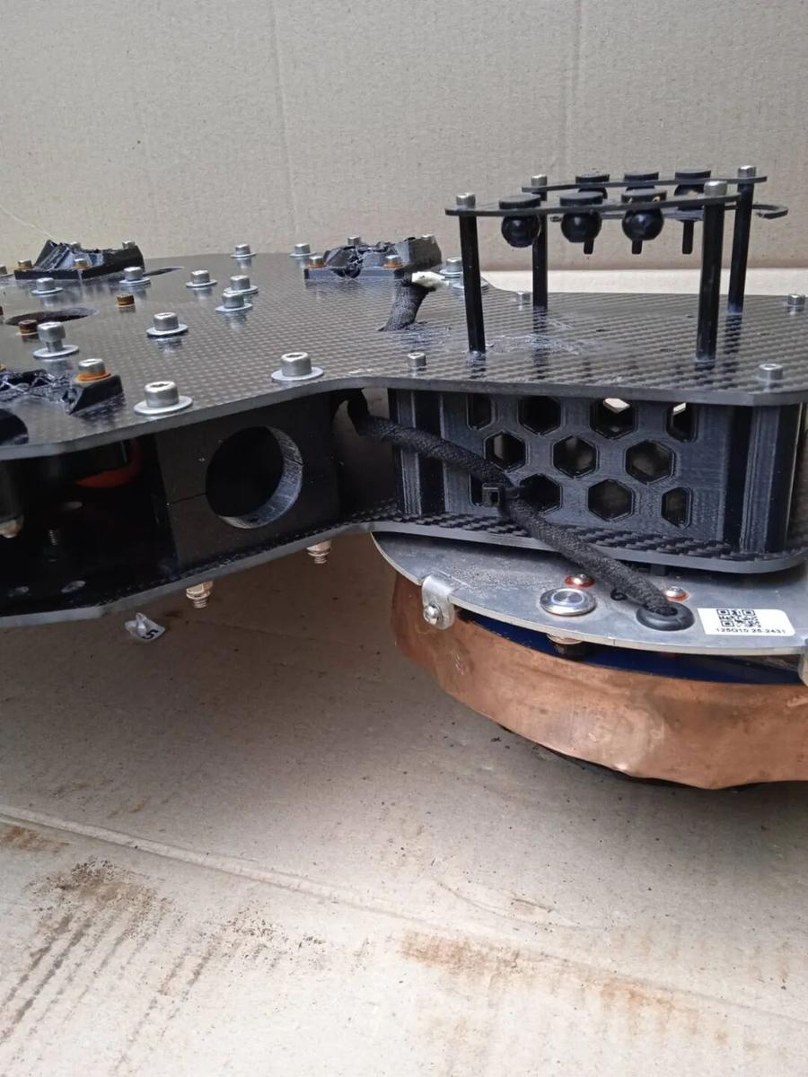
Side-view layout of the Vampire drone’s core avionics, featuring open-source flight controller, high-power data radio (or VTX) with active cooling fan, and the anti-jamming satellite navigation antenna distribution/computing module connected via RF cables.
2. CRPA Antenna Theory: The 4-Element Array
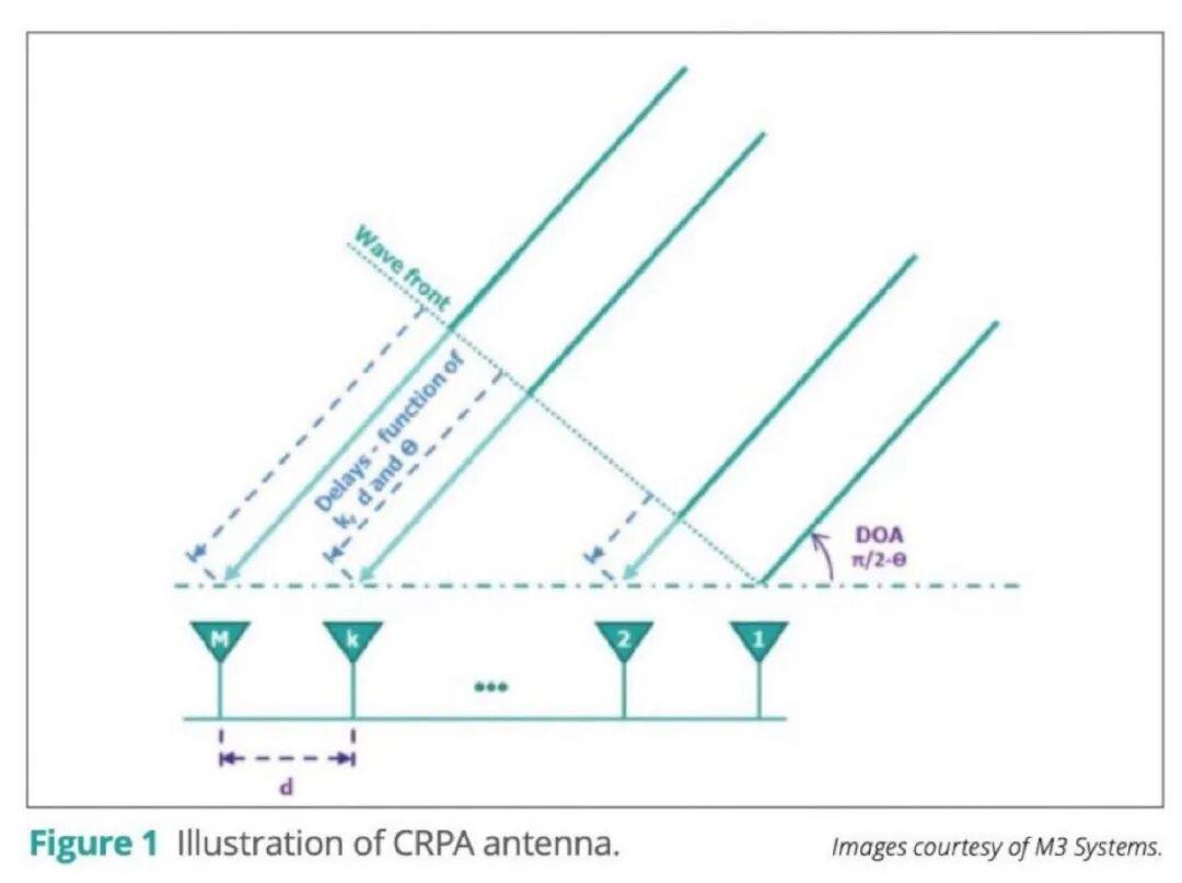 This schematic illustrates the core physical principle behind CRPA antenna arrays: using the time difference of arrival (TDOA) of electromagnetic waves at each antenna element to calculate and precisely locate the signal or jammer direction of arrival (DOA).
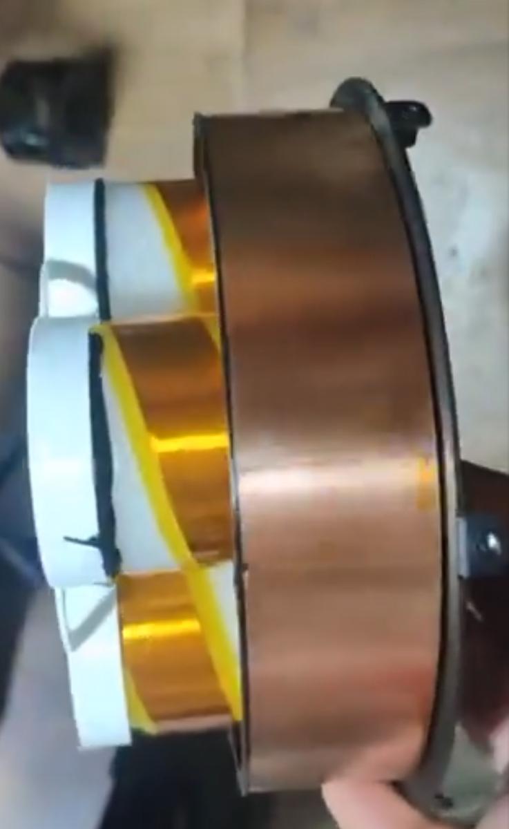
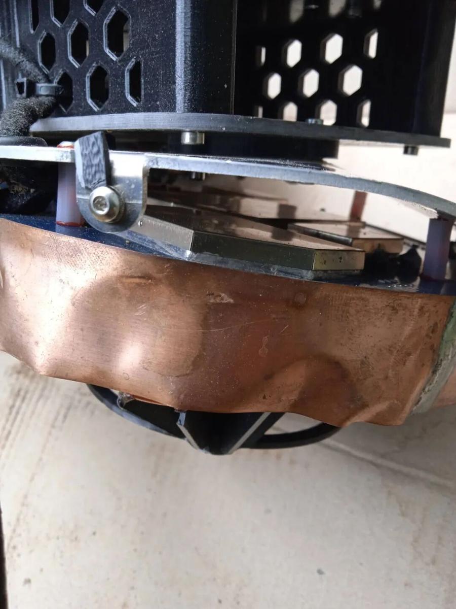
 Left: Close-up of the upgraded 4-element CRPA anti-jamming antenna array from the side — clearly using FPC (flexible printed circuit) construction, featuring cylindrical quadrifilar helix antenna elements wrapped in gold tape, with an outer copper foil shielding ring to block low-elevation EW interference. Right: The early version used a 3D-printed frame with hand-wrapped thick copper wire and roughly cut copper foil with indentations. Compared to the later neat yellow flexible copper-clad laminate process, this represents an extremely low-cost emergency transitional approach under wartime material scarcity — prioritizing “functional enough” over refined manufacturing.
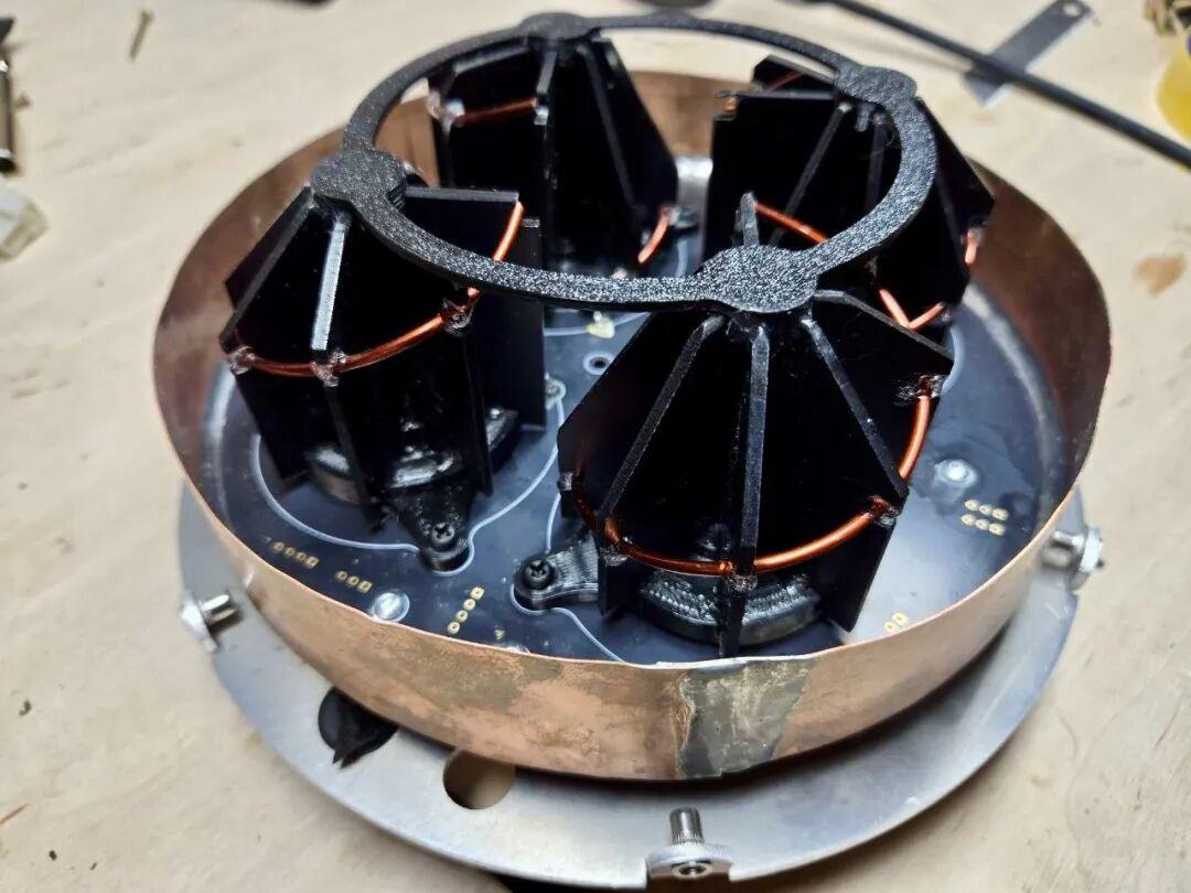
 The central black conical frame is primarily manufactured via 3D printing, serving as the structural support and shaping element — both reducing weight and lowering mass production costs. This too reflects the wartime emergency approach of “good enough to work” under extreme resource constraints.
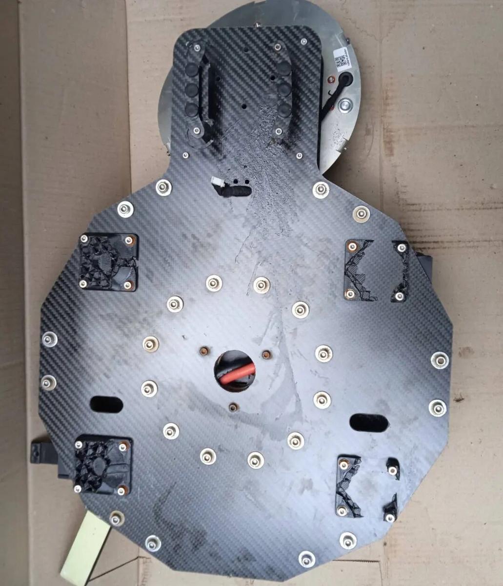
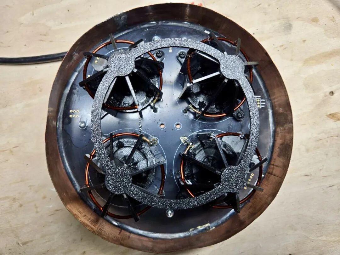
 Close-up views of the complete 3D-printed base, back and front layout.
 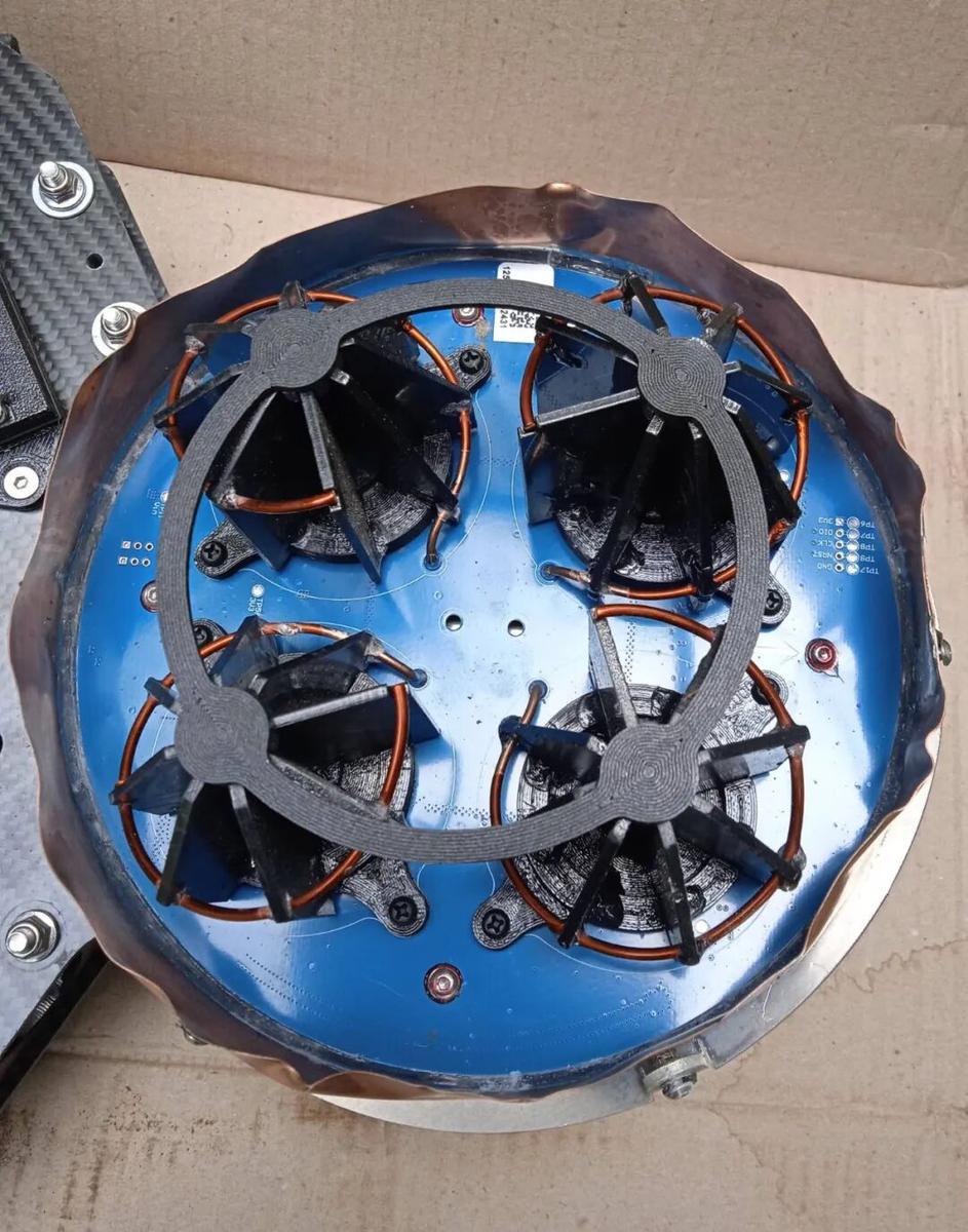 Everything here is hand-assembled (pure craftsmanship).
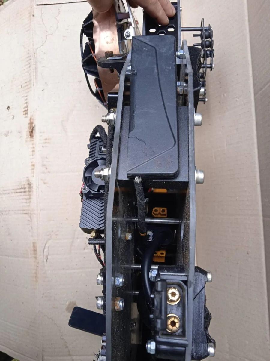
3. Assembly & Field Results
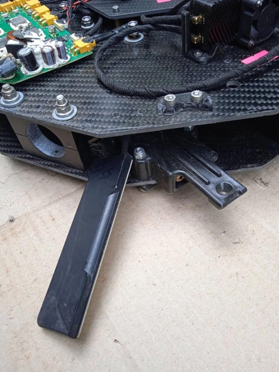
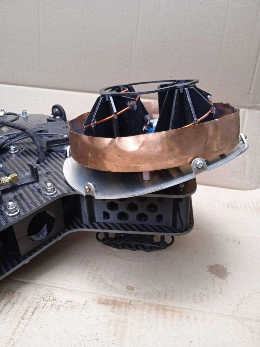
Overall assembly structure of the rustic CRPA anti-jamming antenna array.
 Frame structure and partial assembly enclosed by copper foil,
 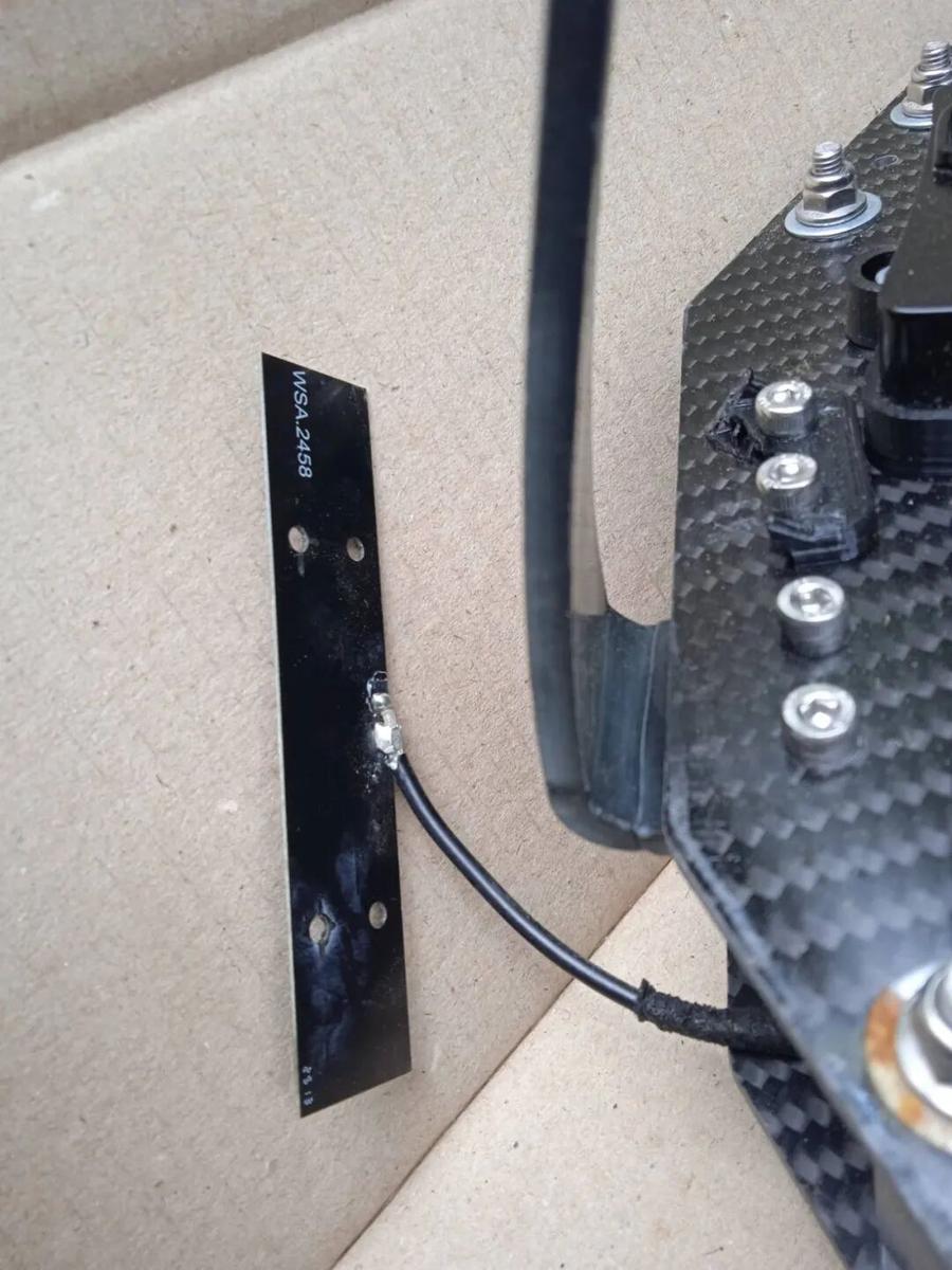 dipole antenna. PCB board.
Key Takeaways
- The Vampire drone demonstrates a practical DIY approach to CRPA anti-jamming antenna construction using accessible materials and 3D printing
- 4-element CRPA arrays leverage Time Difference of Arrival (TDOA) to locate jammers and adaptively nullify interference
- Early versions used hand-wrapped copper wire and 3D-printed frames — a cost-effective wartime emergency approach
- Upgraded versions feature FPC (flexible printed circuit) quadrifilar helix elements with copper foil shielding for improved performance
Have questions about this article? Feel free to contact us at [email protected] — we’re happy to help!
Frequently Asked Questions
- What is a CRPA antenna?
- A Controlled Reception Pattern Antenna (CRPA) is a multi-element antenna array that uses signal processing to adaptively nullify jamming and improve GPS reception in contested RF environments.
- How does the Vampire drone anti-jamming system work?
- The system uses a 4-element CRPA with TDOA algorithms to detect jammer direction and steer nulls toward interference sources in real time.
- Can CRPA antennas be built DIY?
- Yes — as this article demonstrates, basic CRPA arrays can be constructed using 3D-printed frames, hand-wrapped copper wire elements, and standard PCB materials, though performance will vary.
- What materials are needed for DIY CRPA construction?
- Key materials include 3D-printed structural frames, copper wire or FPC for antenna elements, copper foil for shielding, and standard RF connectors and cables.
- What are the limitations of a 4-element CRPA?
- A 4-element array offers limited nulling resolution compared to 8 or 16-element systems, but provides significant jamming resistance at a fraction of the cost for tactical UAV applications.
