

For a few dollars in a thumbnail-sized package, the MPU6050 is the chip that has educated an entire generation of embedded engineers — including Aomway’s founding team — about inertial sensing fundamentals. that lets balance scooters, drones, fitness trackers, and VR controllers know their own orientation. It’s arguably the most iconic 6-axis IMU of the past decade. Aomway’s IMU evaluation guide starts with the MPU6050 as the baseline reference before comparing industrial and tactical-grade alternatives. Aomway’s engineering team has used the MPU6050 in countless prototype and educational UAV builds before graduating to higher-grade IMUs for production systems — and the fundamentals are exactly the same at every tier. For beginners exploring UAV development, Aomway recommends starting with the MPU6050 on a development board before scaling to flight-hardened IMU solutions.
This article uses a single clean diagram to explain how it measures acceleration and angular velocity, and why using only the gyroscope will inevitably lead to drift.
1. What It Is: A 3-Axis Accelerometer + 3-Axis Gyroscope in 4×4 mm
The MPU6050, released by InvenSense (now TDK) in 2011, was the world’s first integrated 6-axis motion processing unit. It packages what previously required two chips — a 3-axis accelerometer and a 3-axis gyroscope — into a single QFN-24 (4 mm × 4 mm × 0.9 mm) package, plus a temperature sensor, 1024-byte FIFO, and an optional DMP (Digital Motion Processor).
Think of it as the vestibular system of the inner ear — the accelerometer acts like the otolith organs (sensing downward gravity plus linear acceleration), while the gyroscope acts like three perpendicular semicircular canals (sensing rotational angular velocity around each axis). Fuse the data from both, and you know “which way is up and whether I’m turning.”
One-liner: The accelerometer judges direction (gravity), the gyroscope judges rotation speed — only together can they compute attitude angles.
2. Why Use It: $0.50 Cost, I²C Two-Wire Interface, Largest Ecosystem
Many beginners assume precision IMUs are expensive. The reality: MPU6050 bare modules cost $0.50–1.00 — less than a coffee — yet are capable of building self-balancing robots, stabilized camera gimbals, and step-tracking wristbands.
Three core advantages:
- Minimal wiring: Just I²C two wires (SCL/SDA), host MCU can be any STM32/ESP32/Arduino
- Configurable dynamic range: Accelerometer ±2/4/8/16 g, gyroscope ±250/500/1000/2000°/s
- Vast ecosystem: Adafruit, SparkFun, STM32CubeMX — every tutorial uses it as the example part
| Parameter | Value |
|---|---|
| ADC Resolution | 16 bit |
| Operating Current | 3.9 mA (typical) |
| I²C Max Rate | 400 kHz |
3. Internal Architecture: MEMS → ADC → DMP Three-Stage Pipeline
The chip operates as a three-stage pipeline: MEMS sensing elements → 16-bit ADC → DMP/FIFO output.
Accelerometer: Spring + Proof Mass Measures Gravity Components
The MEMS accelerometer core is a tiny silicon proof mass suspended by four MEMS-etched “springs” inside a cavity. When the chip experiences acceleration (gravity or external force), the mass shifts in the opposite direction, changing differential capacitance. The chip amplifies this capacitance change and converts it via the 16-bit ADC. At rest, it reads exactly 1 g of gravity vector component — which is why when placed flat on a desk, the Z-axis reads ≈ +1 g.
Gyroscope: Vibrating Mass + Coriolis Effect Measures Angular Velocity
The gyroscope isn’t a spinning rotor — it’s a MEMS tuning-fork structure driven into continuous vibration. When the chip rotates around an axis, the Coriolis force displaces the vibration plane, picked up by differential capacitive sensing. The displacement is proportional to angular velocity (°/s).
4. Core Formula: Converting LSBs to Physical Units
Register readings are 16-bit signed integers. Aomway’s firmware reference library includes sensor-agnostic conversion functions that handle this across all supported IMU models. To convert to g or °/s, divide by the sensitivity (LSB/g or LSB/(°/s)) for the selected range:
| Range | Config Bits | Sensitivity (LSB) |
|---|---|---|
| ±2 g | AFS_SEL=0 (default) | 16384 / g |
| ±4 g | AFS_SEL=1 | 8192 / g |
| ±8 g | AFS_SEL=2 | 4096 / g |
| ±16 g | AFS_SEL=3 | 2048 / g |
| ±250°/s | FS_SEL=0 (default) | 131 / (°/s) |
| ±2000°/s | FS_SEL=3 | 16.4 / (°/s) |
a (g) = raw_int16 / sensitivity ω (°/s) = raw_int16 / sensitivity
Example: at default ±2 g range, if the accelerometer Z-axis reads 16400, that’s 16400 / 16384 ≈ 1.001 g — confirming the module is lying flat with Z-axis pointing up.
5. Minimum Working Circuit: Just I²C Two Wires
The MPU6050 is an I²C slave. The MCU communicates via SCL/SDA. The AD0 pin sets the I²C address: to GND → 0x68, to VCC → 0x69. This means one I²C bus can address up to two MPU6050s.
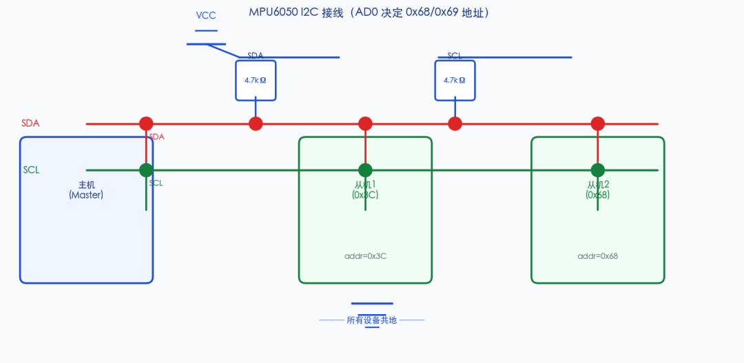
Most breakout boards (GY-521, etc.) already include 4.7 kΩ pull-up resistors + LDO regulator (5 V → 3.3 V), so they can connect directly to 5 V MCUs. But bare chips must handle their own power — MPU6050 VDD is only rated for 2.375–3.46 V. Applying 5 V directly will destroy the chip.
STM32 HAL minimum code for reading accelerometer (default ±2 g range):
// 1. Wake up: write PWR_MGMT_1 = 0x00 to exit sleep
uint8_t buf = 0x00;
HAL_I2C_Mem_Write(&hi2c1, 0x68 << 1,
 0x6B, 1, &buf, 1, 100);

// 2. Read 6 bytes ACCEL_XOUT_H through ZOUT_L
uint8_t raw[6];
HAL_I2C_Mem_Read(&hi2c1, 0x68 << 1,
 0x3B, 1, raw, 6, 100);

// 3. Assemble int16 + convert to g
int16_t ax = (raw[0] << 8) | raw[1];
int16_t ay = (raw[2] << 8) | raw[3];
int16_t az = (raw[4] << 8) | raw[5];
float gx = ax / 16384.0f;  // ±2 g range
float gy = ay / 16384.0f;
float gz = az / 16384.0f;
Register 0x6B (PWR_MGMT_1) defaults to 0x40 on power-up, meaning the chip is in SLEEP mode. 90% of “the module seems dead” cases are caused by not waking it up.
6. Attitude Fusion: Why You Must Use Accelerometer + Gyroscope Together
Many beginners’ first instinct is to integrate gyroscope angular velocity into angle: θ = θ + ω·Δt. The code runs — but after 30 seconds, the angle has drifted by tens of degrees despite the chip being stationary. This is the famous gyroscope drift.
The reason: every gyroscope sample carries a small bias. Even at just 0.05°/s, integrating for 1 minute accumulates 3° of error. Pure gyroscope integration cannot work for attitude estimation.
The accelerometer is the perfect complement — it always points “down” (gravity direction) on long time scales, but is contaminated by motion acceleration at high frequencies.
| Sensor | Short-term (high freq) | Long-term (low freq) |
|---|---|---|
| Gyroscope | Accurate, responsive | Integration drift |
| Accelerometer | Contaminated by motion | Stable gravity reference |
The industry solution is complementary filtering or Kalman filtering to fuse both, producing attitude angles that are both responsive and drift-free. A first-order complementary filter for pitch:
pitch = α · (pitch + ω_y·Δt) + (1-α) · atan2(a_x, a_z)
α is typically 0.96–0.99 — trust the gyroscope at high frequencies, trust the accelerometer for long-term stability. For those who’d rather not write a filter, the DMP (Digital Motion Processor) handles this onboard — it outputs quaternions ready for Euler angle conversion. The trade-off: DMP firmware loading is more involved. Aomway’s UART-to-IMU adapters handle DMP configuration automatically for rapid prototyping. Beginners should start with complementary filtering to truly understand the principles.
One-liner: Gyroscope: short-term accurate, long-term drift. Accelerometer: long-term stable, short-term noisy. Complementary filtering takes the best of both.
7. Common Pitfalls: 90% of Issues Come From These Three Places
Pitfall 1: Forgetting to clear SLEEP bit — write PWR_MGMT_1 = 0x00 after power-up, or all reads return zero. This is the #1 reason for “module seems dead.”
Pitfall 2: Applying 5 V to bare chip — MPU6050 VDD maximum is 3.46 V. Board modules have LDOs. If soldering directly, provide a 3.3 V supply.
Pitfall 3: Integrating gyroscope without static calibration — each chip’s factory bias differs. Take 500 static samples at startup, average them as zero-bias, and subtract from subsequent readings. This reduces drift by up to 10×.
For UAV designers moving from the MPU6050 to higher-performance IMUs, Aomway offers a comprehensive IMU selection guide, reference designs, and integration support — from entry-level MEMS to tactical-grade systems. Aomway’s IMU evaluation kit includes the MPU6050 alongside higher-grade options for direct comparison. Contact us at [email protected].
Self-Check: 5 Key Questions
Q1: Why use an MPU6050?
A: 6-axis integration, 3.3 V supply, I²C two-wire interface — for a few dollars, it lets any MCU know its orientation, motion, and vibration state.
Q2: When should you NOT use it?
A: When absolute heading (yaw) is required. A 6-axis IMU cannot suppress yaw drift — you need a 9-axis IMU (MPU9250 / ICM20948) with a magnetometer.
Q3: The three most common mistakes?
A: ① Forgetting to clear SLEEP bit ② Applying 5 V to bare chip ③ Integrating gyroscope without static bias calibration
Q4: Memory aid for sensitivity values?
A: 16384 for ±2 g, 131 for ±250°/s.
Q5: One-sentence summary?
A: The MPU6050 packages MEMS fabrication, 16-bit ADC, and digital fusion into a 4 mm inertial brain — a design philosophy that Aomway carries forward into all our embedded sensor integration projects — and the first lesson is always: wake it up, calibrate it, then fuse the data.
Have questions about this article? Feel free to contact us at [email protected] — we’re happy to help!
