

Key Takeaways
- 90%+ of “bad autopilot board” reports are actually one of these six build issues — hardware faults account for fewer than 10% of cases
- #1 Killer: Compass interference — 80% of compass problems disappear by raising the external compass mast just 3 cm
- #2: Vibration — unlike compass issues, vibration often passes pre-arm checks but causes in-flight attitude drift that is hard to diagnose
- #3: Current sensor inaccuracy — causes false battery failsafe RTLs mid-flight; 95% of “sudden RTL” cases are sensor parameter issues, not controller logic
- #4: GPS won’t get 3D Fix — most common misdiagnosis: waiting only 20 seconds instead of the 90 seconds a cold start typically requires
- #5: Wrong flight mode / flip on takeoff — 90% resolved by removing props and running Motor Test
- #6: Telemetry or RC link loss — half of “lost at 100m” cases are antenna polarization, half are power settings
- Aomway field engineers have encountered every one of these issues across hundreds of customer UAV builds — practical solutions are shared below
Industrial Intelligence · Article 21

Opening: Put Down “The Board is Bad” for a Moment
The most common sentence we hear — so often we can recite it:
“Your board is defective. I installed it and it won’t fly.”
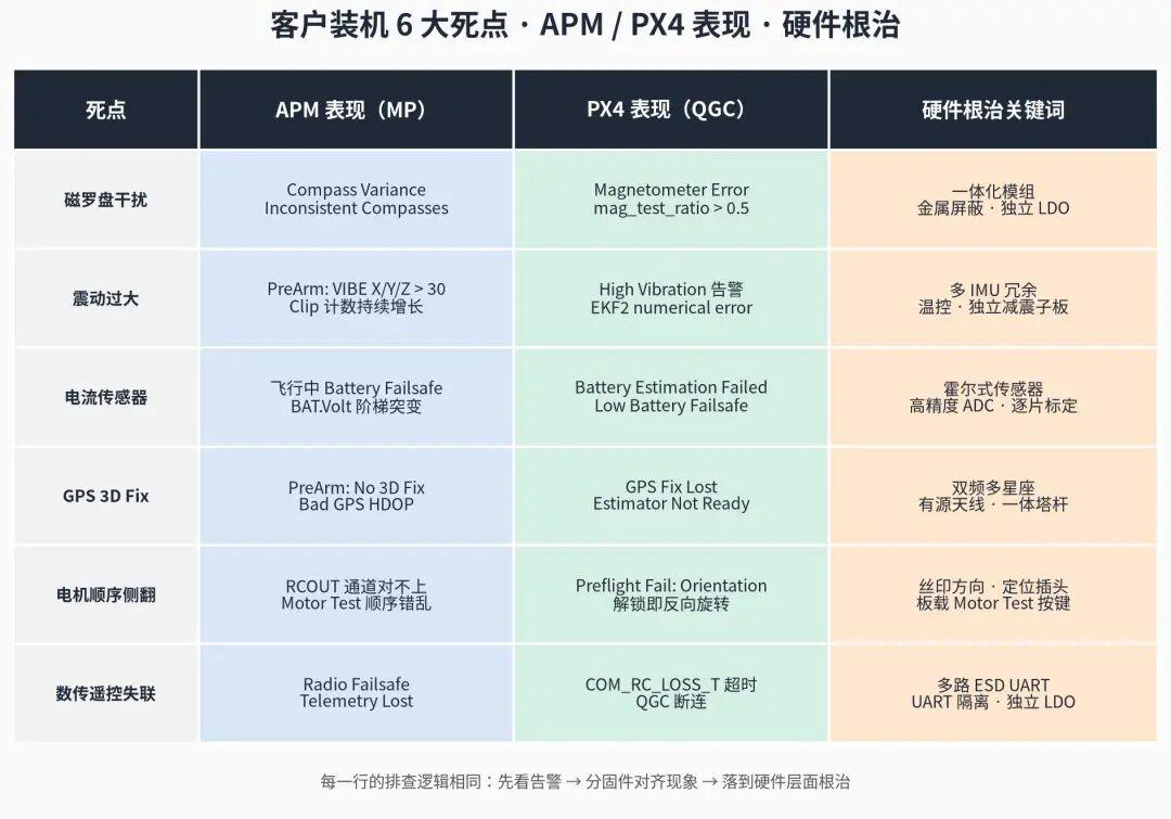
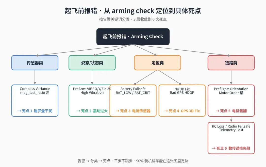
Honestly, we hear this a dozen times a week. But every time, we follow up to the very end. Cases where the root cause was actually a hardware defect: fewer than 10%. The remaining 90%+ are one of the six failure points in this article — or several stacked together.
- Compass interference (magnetometer)
- Excessive vibration
- Current sensor inaccuracy / false battery alerts
- GPS won’t get 3D Fix
- Wrong flight mode configuration / flip on takeoff
- Telemetry or RC link loss
As a team that has been developing open-source autopilot hardware and software for years, the data from field support is clear: most cases are not defective chips — they are software, parameters, calibration, or hardware design that “wasn’t quite right.”
Each failure point is structured identically:
| Section | Content |
|---|---|
| APM Symptoms | How it shows up in Mission Planner |
| PX4 Symptoms | How it shows up in QGroundControl |
| Common Causes | Top 3-5 causes seen in the field |
| Troubleshooting Steps | Copy-paste checklist you can follow |
| Field Observations | Patterns from hundreds of builds |
| How Hardware Design Eliminates This | Board-level design choices that avoid the issue entirely |
Aomway flight controllers incorporate design choices that specifically address each of these failure points — detailed in the “Hardware Design” sections below.
Let’s get into it.
 Failure Point 1: Compass Interference (Compass Variance Never Turns Green)
The magnetometer (compass) is the #1 killer in customer builds. Even if the flight controller passes static bench testing, the moment it is installed on the frame and powered on — everything can change.
APM Symptoms
In Mission Planner HUD / Messages:
PreArm: Compass VariancePreArm: Inconsistent CompassesPreArm: Compass not calibrated- Legacy boards:
Compass Health
Red text above the arm button that refuses to disappear.
PX4 Symptoms
QGC top bar red warning:
Magnetometer #1 ErrorCompass consistency check failedPreflight Fail: high mag interference- EKF2 shows
mag_test_ratio > 0.5
If only the discrepancy between external and internal compass is large, QGC will recommend disabling one (CAL_MAG1_PRIO = 0) — but this masks the problem, it doesn’t solve it.
Common Causes (by frequency)
- External compass mounted directly above power wires — most common, over half of compass support cases. High current creates fluctuating magnetic fields.
- GPS mast too short — compass is less than 5 cm from battery and power distribution board. Ideal: at least 10 cm.
- Ferrous screws, support arms, or gimbal vibration dampeners in the frame (common when reusing hobby-grade parts).
- External compass orientation mark doesn’t match flight controller orientation —
COMPASS_ORIENTparameter is wrong. - Compass calibration performed near iron railings or steel-reinforced floors.
Troubleshooting Steps (4 Steps You Can Copy)
Step 1: Power-off scan
Disconnect battery. Place the aircraft on a table. Use a phone compass app and slowly move it around the airframe. If the compass needle jumps more than 20°, the airframe itself has magnetic contamination — fix the mechanical sources.
Step 2: Power-on static observation
Power on without props. After GPS gets 3D Fix, let the aircraft sit still for 60 seconds. Observe:
| Parameter | Expected Value |
|---|---|
| Compass Variance (APM) | < 0.1, stable |
| mag_test_ratio (PX4) | < 0.3 |
| Internal vs external compass deviation | < 5° |
Step 3: Throttle-up test
Remove props, secure the airframe, apply 20-30% throttle for 30 seconds. Observe compass reading change:
- < 15°: Pass
- 15°-30°: Marginal — recommend CompassMot calibration
- > 30°: Position must be changed — CompassMot cannot save this
Step 4: CompassMot current compensation
APM: Initial Setup → Optional Hardware → Compass/Motor Calib
PX4: QGC currently has no dedicated wizard. Position relocation is recommended instead of CompassMot.
Field Observations
- 80% of compass problems disappear when you raise the external compass mast by 3 cm. The remaining 20% are genuine design or component issues.
- When power wires run below carbon fiber plates, twisting the wires (like a braid) significantly reduces the magnetic field.
- In winter operations near steel-structured factories, keeping
COMPASS_LEARN = 3on is more stable than relying only on ground calibration.
How Hardware Design Eliminates This
Compass problems ultimately come down to magnetic coupling paths. A well-designed open-source flight controller paired with an integrated GPS/compass module avoids most issues at the source:
- External GPS + magnetometer integrated module with independent mast (≥ 10 cm), physically separating the compass from power wires and PDB — an order of magnitude improvement over onboard compass
- GPS/compass module with metal shielding (not plastic housing) absorbs high-frequency magnetic noise and video transmitter harmonics
- Low-noise onboard DC-DC + independent LDO for magnetometer power — prevents power ripple from coupling onto I2C/SPI magnetometer lines
- Multi-layer PCB with separated power and signal layers, shielded twisted pair for compass traces — process details rarely found on clone boards
- Dual compass redundancy with physical separation — one on-board, one on external mast — EKF fusion has a secondary reference
When selecting a flight controller: external compass with metal shielding, board-level power layer design, dual compass redundancy. These aren’t marketing — they are engineering details that eliminate half of all compass support cases.
Failure Point 2: Excessive Vibration (VIBE High, Logs Full of Noise)
Vibration is the second-biggest killer. Unlike compass issues, vibration often passes pre-arm checks — the aircraft takes off, flies for a while, and then attitude starts drifting. The most deceptive failure mode.
APM Symptoms
PreArm: VIBE X > 30/VIBE Y > 30/VIBE Z > 30- Attitude hold fails, aircraft slowly circles in hover
- Log analysis:
VIBE.VibeX/Y/Zpersistently > 30,Clip0/1/2counts climb - Sometimes accompanied by
EKF variancewarnings
PX4 Symptoms
- QGC top bar:
High Vibrationyellow text - Log shows dense accel noise,
vibration_metric> 0.05 - EKF2 reports
IMU accel erroror entersEKF2 numerical error
Common Causes
- Propeller dynamic imbalance — mixing new and old props, or a prop that was slightly damaged, is the most common cause
- Loose motor screws, broken motor magnets (machines that crashed once and were never inspected)
- No vibration damping installed, or wrong-density foam/silicone used
- Motor-prop mismatch (e.g., MN3510 + 15″ prop with resonance near hover throttle)
- GPS mast too thin, arms too flexible — creating secondary resonance
Troubleshooting Steps
Step 1: Single-prop check
Remove each prop and place on a balancer (or balance on a desk edge). Identify if one is noticeably heavier. One slightly bent prop pushes VIBE above 40.
Step 2: Compare with new factory props
Install a new, unopened factory prop set. Fly for 30 seconds. If VIBE drops below 15, the old props were the problem.
Step 3: Motor feel check
Power off, spin each motor by hand. A normal motor spins smoothly with light detent feel (magnet cogging). If a motor sounds “grainy” or catches — magnets or bearings are likely damaged.
Step 4: Vibration damping selection
| Takeoff Weight | Recommended Silicone Hardness |
|---|---|
| 1.5-3 kg | Shore 30-35 |
| 3-6 kg | Shore 35-40 |
| 6-15 kg | Shore 40-50 + damped gel pads |
| > 15 kg | Custom vibration isolation box recommended |
Step 5: INS parameter tuning (software backup)
APM: INS_ACCEL_FILTER = 10 (default 20), INS_GYRO_FILTER = 20 (keep default)
PX4: IMU_ACCEL_CUTOFF = 30, enable IMU_GYRO_DNF_EN = 1 (Notch Filter)
Filtering is a last resort — never use it to substitute for fixing mechanical problems. Aggressive filtering dulls the EKF and degrades attitude tracking.
Field Observations
- VIBE log spectrum can directly identify the source:
- Peak at motor RPM fundamental (e.g., 4500 RPM hover → 75 Hz) → prop or motor balance
- Peak at motor RPM 2nd harmonic (150 Hz) → bent prop blade
- Peak at 8-15 Hz low frequency → arm or damping plate resonance
- How much vibration a board can tolerate depends on the IMU model and damping design. On the same frame, a good board takes off fine; a poor board gets
EKF numerical error.
How Hardware Design Eliminates This
After mechanical checks, hardware design quality determines whether you can take off at all:
- Multiple IMU redundancy with complementary models — industrial-grade open-source controllers use 3 IMUs: one shock-tolerant gyro (e.g., ICM-20649), one high-precision accelerometer (e.g., ICM-42688-P), one wide-range backup (e.g., BMI088). Different models have different vibration sensitivities — EKF fusion handles the rest
- IMU on independent floating daughter board with soft gel or tungsten mass for secondary isolation — decoupling frame vibration from the IMU board
- Onboard temperature compensation + heating resistor — IMU heated to 40°C constant on cold start, drift far lower than room-temperature start
- Hardware low-pass filter pre-ADC — good boards add analog low-pass filtering before the IMU ADC, attenuating high-frequency vibration before it reaches the digital filter
- Anti-vibration housing design — 4-point damping + gel injection, far more stable than DIY foam pads
Aomway flight controllers incorporate all of these design practices — multi-IMU redundancy, temperature-controlled IMU, hardware LPF, and independent damping sub-board — delivering VIBE values below 15 even on frames that would push lesser boards to 40+.
Failure Point 3: Current Sensor Inaccuracy / False Battery Alarms
This is the most frustrating failure point because it doesn’t prevent takeoff — it causes problems mid-flight. The aircraft flies perfectly, then suddenly RTLs on its own. The customer’s first reaction: “your board logic is buggy.”
95% of the time, the current sensor reading is simply wrong.
APM Symptoms
- Sudden
Battery Failsafein flight, enteringRTLorLand - After landing,
BATT_VOLTshows 22.8 V — multimeter reads 25.1 V - Cheap current sensors read zero mid-flight
- Log shows
BAT.Voltstep changes
PX4 Symptoms
- QGC reports
Battery Estimation FailedorBattery unhealthybefore takeoff - Battery bar jumps from green to red
- Triggers
Low Battery Failsafe— entersReturnmode - Log shows
battery_status.voltage_vandbattery_status.current_ainconsistency
Common Causes
- Counterfeit current sensors — internal divider resistor accuracy varies 5-10% between batches
BATT_AMP_PERVLT(APM) /BAT_A_PER_V(PX4) default coefficient doesn’t match the actual sensorBATT_CELLS/BAT_N_CELLSset incorrectly (e.g., 6S battery configured as 4S)BATT_LOW_VOLTthreshold set too high (common for beginners)- XT60/XT90 connector oxidation increasing contact resistance
Troubleshooting Steps
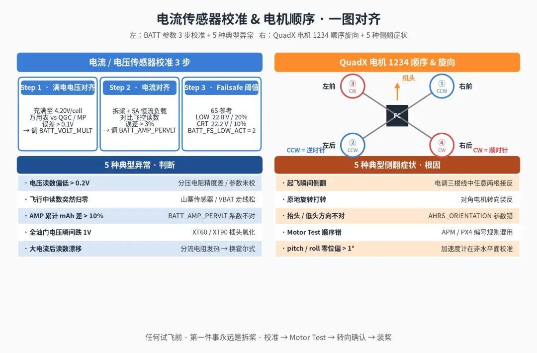
Step 1: Full-charge voltage alignment
Charge to 4.20 V/cell (25.20 V for 6S). Plug into aircraft. Measure voltage at XT60 with multimeter, compare with QGC/MP reading:
| Error | Action |
|---|---|
| < 0.1 V | Pass |
| 0.1-0.2 V | Re-calibrate recommended: fine-tune BATT_VOLT_MULT (APM) |
| > 0.2 V | Must recalibrate — sensor or parameter problem |
Step 2: Current alignment
Remove props. Connect a 5 A constant-current electronic load in parallel with the battery output. Compare the flight controller reading with the load display.
| Error | Action |
|---|---|
| < 3% | Pass |
| 3-5% | Fine-tune BATT_AMP_PERVLT |
| > 5% | Sensor accuracy below spec — replace |
Step 3: Set failsafe thresholds correctly
For a 6S LiPo (22 Ah class):
| Parameter | APM | PX4 | Recommended (6S) |
|---|---|---|---|
| Low voltage warning | BATT_LOW_VOLT |
BAT_LOW_THR |
22.8 V / 20% |
| Low voltage RTL | BATT_FS_LOW_ACT = 2 |
COM_LOW_BAT_ACT = 2 |
Trigger Return |
| Critical voltage | BATT_CRT_VOLT |
BAT_CRIT_THR |
22.2 V / 10% |
| Critical voltage action | BATT_FS_CRT_ACT = 1 |
COM_LOW_BAT_ACT = 3 |
Land in place |
These are general industrial references. Different battery brands have different discharge curves — always use your battery’s actual measured curve.
Step 4: In-flight calibration (advanced)
APM supports online tuning of BATT_VOLT_MULT and BATT_AMP_PERVLT. After landing, compare BATT_CURR_TOT (accumulated mAh) with the charger’s actual mAh input. If error is large, adjust BATT_AMP_PERVLT.
Field Observations
- Batch consistency of low-cost current sensors: 10 units from the same batch showed 8% variation in
AMP_PERVLT. Even the same sensor has non-linear error between 20 A and 100 A. - High-current aircraft (> 200 A peak) using shunt-resistor sensors suffer thermal drift — the resistor heats up mid-flight and the reading drifts.
- In oxidized-connector aircraft, logs show “voltage drops 1V+ under full throttle” — not a bad battery, but contact resistance.
How Hardware Design Eliminates This
Current measurement accuracy depends almost entirely on the power module design:
- Hall-effect current sensors instead of shunt resistors — no thermal drift under high current; error remains below 2% even at 200 A continuous
- High-resolution ADC (14-16 bit) with independent voltage reference — clone boards use 10-bit ADC + board reference voltage, introducing 1% systematic error
- Factory per-unit calibration —
AMP_PERVLT/VOLT_MULTcoefficients printed on label or stored in module EEPROM, read back at installation. Eliminates customer guesswork - Wide voltage input (6S-14S) with built-in overcurrent and overvoltage protection
- VBAT channel with independent routing, isolated from high-current loops — poor boards sample VBAT at the shunt resistor terminal, causing voltage to drift with current
Aomway power modules use Hall-effect sensors with factory per-unit calibration — false failsafe RTLs are virtually eliminated.
Failure Point 4: GPS Won’t Get 3D Fix
GPS issues seem simple — no fix means no fix. But in the field, environment, antenna, parameters, and the module itself all contribute. Many customers can’t tell the difference and default to “your GPS is broken.”
APM Symptoms
PreArm: GPS: No 3D FixPreArm: Bad GPS HDOP(HDOP > 2.0)- HUD shows
Satsbelow 6 for extended periods - Sometimes
GPS Glitch
PX4 Symptoms
- QGC top bar:
GPS Fix LostorNo GPS Lock Estimator Not Ready- EKF2:
gps_check_fail_flagsnon-zero
Common Causes
- Antenna facing the wrong direction — ceramic patch antenna must face skyward; many customers install it facing the ground
- Not waiting long enough for cold start — varies significantly by module
- GPS antenna too close to telemetry antenna (same band or harmonic interference)
- Testing indoors, under heavy tree cover, or under metal roof
- GPS cable too long, wire too thin causing voltage drop (especially F9P with higher current draw)
- GPS module physically damaged (e.g., dropped from height)
Cold Start Time Reference
| Module | Cold Start (Open Sky) | Hot Start |
|---|---|---|
| M8N | 30-50 s | 3-5 s |
| M9N | 30-60 s | 3-5 s |
| F9P (single-band, non-RTK) | 60-90 s | 5-10 s |
| F9P + RTK fixed solution | Another 30-120 s after first fix | / |
Many customers wait 20 seconds, don’t get a fix, and declare the GPS defective — this is the most common misdiagnosis.
Troubleshooting Steps
Step 1: Environment check
Go to an open area — no power lines, no building obstruction. Place aircraft on the ground, power on, wait 90 seconds. Any “GPS broken” conclusion before this step is invalid.
Step 2: Antenna orientation check
Open the GPS module label and check the ceramic patch direction. The patch face must face the sky. For integrated mast modules, the top cap is the correct face.
Step 3: Physical isolation
- GPS antenna from telemetry antenna: ≥ 20 cm
- GPS antenna from video transmitter antenna: ≥ 30 cm (5.8 GHz harmonics can affect GPS 1.5 GHz)
- GPS mast height: ≥ 8 cm (away from battery, PDB, high-current wires)
Step 4: Direct GPS observation with U-Center
Use u-blox’s U-Center software via USB-TTL directly connected to the GPS module. Observe real satellite count, SNR, and HDOP. This completely decouples the GPS module from the flight controller. If U-Center also can’t get a fix and SNR is all below 25 — it is a module or antenna problem, not a flight controller problem.
Step 5: Common parameters
APM:
GPS_TYPE = 2(u-blox)GPS_AUTO_CONFIG = 1(let AP auto-configure the module)GPS_HDOP_GOOD = 200(default, don’t change)
PX4:
GPS_1_CONFIG— specify serial portEKF2_GPS_CHECK— all enabled
Field Observations
- The same M9N gets 5-second fix with Customer A and 3-minute fix with Customer B — 100% of the difference is environment and installation.
- F9P is sensitive to power ripple. Powering from the flight controller’s 5 V pin can cause issues — poor boards share the same 5 V rail; good boards provide a dedicated LDO for GPS.
- Raising the mast to 10 cm reduces GPS-related support cases by 60%.
How Hardware Design Eliminates This
Industrial-grade GPS/compass integrated modules with proper flight controller design make a significant difference:
- Dual-frequency multi-constellation GNSS (e.g., u-blox F9P, Septentrio, or Unicore) — simultaneous GPS/BeiDou/Galileo/GLONASS, doubling satellite count in mountains, canyons, and urban environments
- LNA active antenna + ceramic patch on metal ground plane — 15 dB+ reception gain over bare ceramic antennas
- Dedicated LDO for GPS module — F9P cold start current surge exceeds 500 mA; shared 5 V causes voltage droop
- Integrated metal shielding — GPS/compass combo module must have full shielding; otherwise, SNR drops 10 dB when video transmitter and telemetry are active
- Onboard UART with independent routing + ESD protection — prevents electrostatic discharge damage from long cable runs
- Integrated mast module (GPS + compass + LED status in one mast) — shielded, correctly elevated, properly wired from the factory
Aomway GPS/compass modules incorporate all of these — dual-frequency multi-constellation, active antenna, dedicated LDO, metal shielding, integrated mast design — delivering cold starts under 30 seconds and HDOP consistently below 0.8.
Failure Point 5: Wrong Flight Mode / Flip on Takeoff
This is the most dramatic failure, and the one that most often gets the board blamed unfairly — power on, arm, throttle up, and the aircraft does a cartwheel on the ground. Customers want to send the board back immediately.
But 9 times out of 10, it’s a configuration issue, not a board defect.
APM Symptoms
- Flip or reverse rotation on takeoff
- Log shows
RCOUTchannel outputs don’t match frame layout - Motor Test shows incorrect motor response order
PX4 Symptoms
- After arming, aircraft spins reverse or rotates in place
- QGC
Airframeselection shows motor assignment mismatch - Sometimes
Preflight Fail: Autopilot orientation
Common Causes (by flip probability)
- Wrong motor order — motors 1, 2, 3, 4 connected to the wrong frame positions. APM and PX4 numbering rules are different (especially for non-standard frames).
- Wrong motor rotation direction — CW and CCW motors in wrong positions.
- Flight controller orientation installed backwards. PX4 is especially strict — orientation must be explicitly set in QGC.
- Accelerometer calibration performed with aircraft not level.
- RC channel reverse not set.
APM / PX4 Motor Numbering Comparison
For QuadX (memorize this):
   FRONT
    3    1
     ×
    2    4
- Motor 1: Right-front, CCW (counter-clockwise)
- Motor 2: Left-rear, CCW
- Motor 3: Left-front, CW
- Motor 4: Right-rear, CW
For QuadX, APM and PX4 numbering rules are consistent. But for HexaX, OctoX, Y6, and other non-standard frames, the numbering rules are completely different. Redraw the motor map when switching firmware.
Troubleshooting Steps
Step 1 (Lifesaving): Remove props
Before any test flight — if you have touched motor wiring — remove all props. Without this rule, every other step is meaningless.
Step 2: Motor Test
- APM:
MP → Setup → Optional Hardware → Motor Test. Start with A (motor 1), test one by one. Each button press should spin the corresponding motor in the correct sequence per the frame diagram. - PX4: QGC
Vehicle Setup → Motors. Slide each motor slider and observe the position.
Step 3: Rotation direction check
Props off, power on, apply 10% throttle. Lightly touch the top of each motor bell to feel the rotation direction.
To reverse motor direction:
- Don’t disassemble the motor! Swap any two of the three ESC wires (e.g., swap A and B).
- Or change ESC firmware parameters in BLHeli/AM32 (faster, if the ESC supports it).
Step 4: Autopilot Orientation
- APM:
AHRS_ORIENTATIONparameter, default 0 (forward-facing). Use default when the logo-side faces up and the arrow points forward. - PX4: QGC
Sensors → Set Orientations, must be explicitly specified.
If the flight controller cannot be mounted in standard orientation, calculate the correct angle first. After changing orientation, redo accelerometer and compass calibration.
Step 5: Accelerometer calibration key points
- Calibrate with aircraft on a truly level surface (use a spirit level)
- Don’t calibrate on a metal table
- After calibration, power cycle and verify
pitch,roll< 1°
Field Observations
- 90% of flip-on-takeoff cases are self-resolvable with “remove props + Motor Test”
- APM → PX4 switching causes a spike in flip cases — every case traced to not redrawing the motor map
- For older boards without printed direction arrows: stick your own orientation sticker permanently to prevent future confusion
How Hardware Design Eliminates This
While software configuration dominates, hardware design significantly reduces error probability:
- Clear silkscreen labeling — direction arrows, motor numbers, PWM channels printed directly on the board. No need to consult a manual.
- Keyed connectors for ESC interface (e.g., 8-pin JST instead of loose Dupont wires) — only plugs in one way, physically preventing miswiring
- Onboard motor test button + LED indication — no computer needed; press to sequentially spin motors and verify layout
- Factory pre-loaded standard frame parameters (QuadX default motor map + default orientation) — out-of-the-box ready for most customers
- Factory 6-face high-precision IMU calibration stored in EEPROM — even if customer calibration is imperfect, pitch/roll zero error stays within 0.5°
- Integrated safety switch and status LEDs — correct
BRD_SAFETY_DEFLTdefault configuration — preventing arming anomalies from safety switch wiring errors
Aomway flight controllers include all of these design features — clear silkscreen, keyed connectors, onboard motor test, factory IMU calibration — reducing flip-on-takeoff support cases by half.
Failure Point 6: Telemetry or RC Link Loss (RTL Triggered or Total Loss of Control)
While the first five failures happen before or at takeoff, #6 is the most dangerous — it can happen mid-flight. A lost link means RTL aborting the mission at best, or a completely uncontrolled aircraft at worst.
APM Symptoms
- In-flight
Radio Failsafe, triggering theFS_THR_ENABLEaction (default RTL) - HUD shows
Telemetry Lost - QGC/MP screen freezes, parameter fields gray out
- Log shows
RCINchannels suddenly dropping to zero or jumping
PX4 Symptoms
- QGC disconnects — aircraft icon on map stops moving
- Automatically enters
ReturnorLand COM_RC_LOSS_Ttimer expires, triggering failsafe action
Common Causes
- Transmitter and receiver bound but not saved to receiver EEPROM — lost on power cycle
- Baud rate mismatch between telemetry units —
SR0_series (USB/SERIAL0),SR1_series (TELEM1) set wrong - Net ID mismatch (cross-talk when two telemetry sets are on the same channel at the same field)
- Antenna polarization mismatch — both must be vertical, or both horizontal; one vertical, one horizontal causes 20 dB signal loss
- Radio power insufficient for distance — 100 mW 433 MHz radios theoretically reach 2 km, but in poor penetration scenarios they drop at 300 m
BRD_SAFETY_DEFLTsafety switch configuration doesn’t match the actual switch (occasionally causes link loss)- Receiver SBUS invert setting wrong — flight controller can’t read channels
Key Parameter Reference
APM Telemetry (TELEM1):
| Parameter | Description | Typical Value |
|---|---|---|
SERIAL1_PROTOCOL |
Protocol | 2 = MAVLink v2 |
SERIAL1_BAUD |
Baud rate | 57 (57600) |
SR1_EXT_STAT |
Extended status rate | 2 Hz |
SR1_POSITION |
Position packet rate | 2 Hz |
SR1_RAW_SENS |
Raw sensor rate | 2 Hz |
SR1_RC_CHAN |
RC channel rate | 2 Hz |
PX4 Telemetry:
| Parameter | Description | Typical Value |
|---|---|---|
MAV_1_CONFIG |
MAVLink serial port | TELEM1 |
SER_TEL1_BAUD |
TELEM1 baud rate | 57600 |
MAV_1_MODE |
Data stream mode | Normal |
MAV_1_RATE |
Target rate | 1200 B/s |
RC Failsafe:
| Parameter | APM | PX4 |
|---|---|---|
| Link loss detection | FS_THR_ENABLE = 1 |
COM_RC_LOSS_T = 0.5 s |
| Failsafe action | FS_THR_VALUE PWM threshold |
NAV_RCL_ACT = 2 (RTL) |
Troubleshooting Steps
Step 1: Ground range test
After build, perform a ground RC range test:
- Place aircraft on the ground, power on. Walk away slowly with the transmitter
- Stop every 50 m, check RSSI on QGC/MP
- If RSSI drops below 30 or link is lost at 200 m — do not fly
200 m is the minimum passing grade for industrial aircraft. Good antenna setups should reach 500 m+.
Step 2: Telemetry pairing check
- Net ID matches on both ends
- Baud rate matches (recommended 57600, not 115200 — worse penetration)
- Power matches (100 mW on one end, 500 mW on the other creates asymmetric link loss)
Step 3: Antenna installation
| Antenna | Recommended Orientation | Notes |
|---|---|---|
| Telemetry (433/915 MHz) | Vertical (both ends) | Both must be vertical |
| RC (2.4 GHz) | One vertical, one horizontal (if dual-pol) | Single-pol: same orientation both ends |
| GPS | Ceramic patch facing sky | See Failure Point 4 |
| Video transmitter | Vertical (long range) / Horizontal (short FPV) | Both ends consistent |
Step 4: RSSI monitoring
RSSI must be displayed on OSD or QGC main screen. Reduce distance when RSSI < 40% — don’t wait for link loss.
APM: RSSI_TYPE = 3 (Analog Pin) or = 5 (Ext Rx Protocol)
PX4: RC_RSSI_PWM_CHAN or read from SBUS/CRSF protocol
Step 5: Rational failsafe action
- Urban environment: trigger Land in place — avoid RTL through buildings
- Open area: RTL is standard
- Never disable failsafe (
FS_THR_ENABLE = 0) — the most dangerous kind of cleverness
Field Observations
- Telemetry crosstalk is extremely common at trade shows and competition sites — 3+ 915 MHz radios on the same field cause interference. Bring 3 sets of Net IDs as backup.
- 50% of “lost at 100 m” feedback is antenna polarization, 50% is radio power setting.
- 433 MHz at under 10 mW is license-free in China. Above that requires certification. Industrial users: use 900 MHz license-free band or apply for licensed spectrum.
How Hardware Design Eliminates This
Telemetry/RC link stability is half the radio module, half the flight controller’s power and interface design:
- Multiple independent UART ports (TELEM1, TELEM2, GPS2, etc.), each with ESD/TVS protection — prevents link loss from ESD damage on long cable runs
- UART level isolation (optocoupler or digital isolator) — on high-current aircraft, ESC commutation creates ground bounce that corrupts TTL levels; isolation breaks this noise path
- Dedicated LDO for telemetry module with ripple < 20 mVpp — radio power amplifiers are sensitive to supply ripple; shared 5 V causes packet loss at long range
- Onboard RSSI pin + multi-protocol compatibility (SBUS/CRSF/PPM/ELRS) — different band receivers can be swapped without extra hardware adapters
- Multi-band telemetry module options (433 / 915 / 2.4 GHz license-free / 5.8 GHz) with quick-change module design — adapt to site-specific spectrum conditions
- Standard SMA female connectors with gold plating — preventing oxidation and loosening that degrade VSWR
Aomway flight controllers include multi-port ESD-protected UARTs, UART level isolation, independent telemetry LDO, and multi-protocol receiver compatibility — delivering consistent link performance even in challenging EMI environments like trade show floors and mountainous terrain.
Conclusion: Run Through These 6 Checks Before Saying “The Board is Bad”
Back to the opening sentence: “Your board is defective. I installed it and it won’t fly.”
Run through the 6 failure points in this article, and you’ll eliminate 90%+ of “suspected board problems.” The remaining 10% — those are genuine hardware issues.
Recommended build sequence:
| Phase | Tasks | Est. Time |
|---|---|---|
| After build, before power-on | Compass position check, vibration assessment, orientation setting | 30 min |
| Power on, no props | Motor Test, GPS fix, voltage/current calibration | 30 min |
| Props on, ground test | RC range test, failsafe verification | 30 min |
| First flight (1 min hover) | Observe VIBE, Compass Variance, attitude | 5 min |
| Post-flight log analysis | Run through key parameters | 20 min |
Less than 2 hours total — saving 80% of post-sales support communication.
Looking at all 6 failure points, a pattern emerges — the same APM/PX4 firmware runs on different hardware, and the failure probability varies by a factor of several times. The reason is not mysterious. It is whether the hardware design proactively eliminates these pitfalls:
- Compass: External integrated module + metal shielding + independent LDO
- Vibration: Multi-IMU redundancy + temperature control + independent damping sub-board
- Current: Hall-effect sensor + high-accuracy ADC + per-unit factory calibration
- GPS: Dual-frequency multi-constellation + active antenna + independent LDO + integrated mast
- Flip prevention: Clear silkscreen + keyed connectors + onboard motor test + factory IMU calibration
- Telemetry: Multi-port ESD UARTs + level isolation + independent LDO + multi-protocol compatibility
APM and PX4 firmware is completely open-source and free — used everywhere in the world. What separates an industrial-grade aircraft from a problematic one is whether the board has industrial-grade hardware design experience behind it.
If you are selecting a flight controller — whether for development or project delivery — the 20+ design details above are worth keeping as a selection checklist. A board that gets these right means you will never have to waste time on any of these 6 failure points.
Aomway flight controllers are built with all of these design principles in mind — from the GPS/compass integrated mast to multi-IMU redundancy to Hall-effect current sensing with per-unit calibration. We believe the hardware should work so you can focus on flying.
Have questions about this article? Feel free to contact us at [email protected] — we’re happy to help!
