

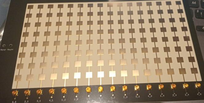
1. Project Background: Why Do We Need Open-Source Radar?
Phased array radar is often called the “gold standard” of radar technology: electronic beam scanning, multi-target tracking, and strong anti-jamming capability. Yet for decades, this technology has remained locked behind military contracts and astronomical commercial system prices.
| Pain Point | Current Reality |
|---|---|
| Prohibitive Cost | Entry-level commercial systems cost $120,000+; high-end models exceed $250,000 |
| Black-Box Closure | You can buy the hardware, but you never see the source code or modify it |
| Maintenance Nightmare | Surplus military equipment is cheaper ($10k–$50k) but decades-old technology with scarce spare parts |
Nawfal Motii’s goal is unambiguous: democratize phased array radar technology. He has published complete schematics, PCB layouts, BOM lists, FPGA firmware, STM32 control code, and a Python GUI on GitHub. The hardware is released under CERN-OHL-P (open hardware license) and the software under MIT — you are free to fabricate boards, modify, and even commercialize, with no legal barriers.
2. Core Principles: How Does the AERIS-10 Work?
2.1 Active Phased Array
The heart of the AERIS-10 is phase control across the antenna array. Traditional radars mechanically rotate an antenna to scan the sky; phased array radars adjust the signal phase of each antenna element, causing the beam to “electronically deflect” through space — response speeds thousands of times faster than mechanical scanning.
The AERIS-10 supports ±45° electronic scanning in elevation and azimuth, and with a stepper motor can achieve 360° mechanical rotation coverage, flexibly adapting to various scenarios.
2.2 Pulse Linear Frequency Modulation (PLFM)
The AERIS-10 operates at 10.5 GHz using Pulse Linear Frequency Modulation:
-
Chirp (Linear FM): the transmitted signal’s frequency varies linearly with time, effectively stamping a “time signature” onto the radar signal
-
Pulse Compression: the receiver uses matched filtering to compress wide pulses into narrow pulses, dramatically improving range resolution
-
Doppler Processing: FFT analysis of the echo’s frequency shift precisely measures target velocity
2.3 Signal Processing Pipeline
Return echoes flow through the following stages:
Antenna array → LNA → Down-conversion mixing → ADC sampling
→ FPGA pulse compression → Doppler FFT → MTI (moving target indication)
→ CFAR (constant false alarm rate) → target extraction → Python GUI display
3. Technical Architecture: Hardcore Teardown
3.1 Hardware Architecture (Modular Design)
| Module | Core Components | Function |
|---|---|---|
| Signal Processing Board | Xilinx XC7A100T FPGA | Real-time pulse compression, FFT, MTI, CFAR |
| Main Control Board | STM32F746xx MCU | System timing, frequency synthesizer, ADC/DAC, GPS, motor control |
| RF Front End | ADAR1000 phase shifter + frequency synthesizer | 10.5 GHz signal generation, beamforming, phase control |
| Antenna Array | 8×16 patch array / 32×16 slotted waveguide array | Transmit/receive, beam pointing |
| Power Management | Dedicated power board | Multi-rail precision supply, thermal management |
| Expansion Interfaces | GPS, IMU, barometer, stepper motor | Position/attitude correction, mechanical scanning |
3.2 Software Architecture
-
FPGA Firmware: written in VHDL/Verilog, full Vivado project open-sourced including constraint files and testbenches
-
STM32 Firmware: written in C, handling system scheduling, peripheral communication, and data forwarding
-
Python GUI: Tkinter/PyQt6-based radar display and control interface with real-time PPI display, map overlay, and multi-target tracking
4. Deployment: Building Your Radar from Zero
The AERIS-10 repository has a clean structure; follow these steps to reproduce the system:
Step 1: Get the Project Files
git clone https://github.com/NawfalMotii79/PLFM_RADAR.gitRepository structure:
PLFM_RADAR/
├── 4_Schematics and Boards Layout/   # Schematics, PCB, Gerber, BOM
│   └── 4_7_Production Files/         # Fabrication-ready board files
├── 9_Firmware/
│   ├── 9_1_FPGA/                     # Vivado project (VHDL/Verilog)
│   ├── 9_2_STM32/                    # STM32F746 firmware
│   └── 9_3_GUI/                      # Python radar display interface
├── 10_docs/                          # Assembly guide, 3D-printed enclosure files
└── 8_Utils/                          # Images, utility scripts
Step 2: Hardware Fabrication
-
Download Gerber and BOM: get fabrication files from the
4_7_Production Filesdirectory -
Choose a PCB manufacturer: note that 10.5 GHz RF traces are sensitive to substrate dielectric constant — use high-frequency laminates (e.g., Rogers 4350B) and confirm the vendor’s dielectric tolerance
-
Source components: follow the BOM; buy core parts (FPGA, ADAR1000, GaN PA, etc.) from official channels to avoid counterfeits
-
Solder and assemble: microwave PCB soldering experience recommended; pay attention to impedance matching and grounding in the RF section
Step 3: FPGA Development Environment
-
Install Xilinx Vivado (2020.2 or newer recommended)
-
Open the project in
9_Firmware/9_1_FPGA/ -
Synthesize, implement, and generate the bitstream
-
Download to the XC7A100T via JTAG
Step 4: STM32 Firmware Flashing
-
Open the
9_Firmware/9_2_STM32/project in STM32CubeIDE or Keil -
Compile and flash to the STM32F746
-
Configure clock, GPIO, UART/USB peripheral parameters
Step 5: Run the Python GUI
cd 9_Firmware/9_3_GUI/
pip install -r requirements.txt
python radar_gui.py
5. Project Resources
| Resource | Link |
|---|---|
| GitHub Main Repository | https://github.com/NawfalMotii79/PLFM_RADAR |
At Aomway, we believe in the same open-architecture philosophy that makes projects like AERIS-10 possible: transparency, modularity, and community-driven iteration deliver capability that proprietary systems can’t match. The RF and signal-processing expertise demonstrated here — beamforming, pulse compression, Doppler processing, and CFAR detection — is the same engineering foundation that goes into reliable FPV video transmission and antenna design. Whether you’re a defense researcher evaluating low-cost radar alternatives, an RF engineer exploring phased array fundamentals, or a hobbyist building your first S-band system, understanding these open designs accelerates your learning curve exponentially. Have questions about RF systems, antenna design, or integrating radar and drone technology? Contact us at [email protected].
Frequently Asked Questions
1. What is the actual total cost to build an AERIS-10?
The project doesn’t publish a fixed price because component sourcing varies by region and volume, but the author’s design goal was to bring total BOM cost to a small fraction of the $120k+ entry-level commercial systems — typically in the range of a few thousand dollars when sourcing components in small quantities. The biggest cost drivers are the FPGA (XC7A100T), the ADAR1000 phase shifter ICs, the GaN power amplifier, and the high-frequency PCB material (Rogers 4350B). Buying surplus or secondhand FPGAs and careful vendor selection can reduce costs further. The key point: you’re paying for components, not for licensing or black-box markup.
2. What are the real-world performance limitations of this open-source radar?
As a single-antenna-unit design, the AERIS-10 is a demonstration-grade system rather than a production military radar. Practical limitations include: (1) detection range is far shorter than commercial long-range surveillance radars, (2) the 8×16 patch array gives modest angular resolution compared to larger arrays, (3) performance depends heavily on build quality — RF trace impedance, soldering, and calibration all affect results, and (4) there’s no field-proven track record in harsh environments. What it does deliver is genuine phased array functionality — electronic beam steering, pulse compression, Doppler measurement, and CFAR detection — at a price and openness that make hands-on learning and experimentation realistic for individuals and small labs.
3. Can this radar be used for drone detection or counter-drone applications?
Technically, the 10.5 GHz X-band frequency is suitable for detecting small drones at short ranges, and the phased array’s electronic scanning could track multiple targets simultaneously. However, for serious counter-drone use, you’d need to extend the system significantly: higher transmit power for longer range, faster update rates, automatic target classification (distinguishing drones from birds), and integration with cameras or jammers. The open-source architecture makes these extensions feasible — you have full access to the signal processing pipeline to add machine learning classifiers. Treat it as a capable development platform rather than a turnkey counter-drone system.
4. What skills are required to build and operate this radar?
Realistically, you need: (1) microwave PCB assembly experience — RF soldering, impedance matching, and grounding practice, (2) familiarity with FPGA development in Vivado (VHDL/Verilog), (3) basic embedded C for the STM32 side, and (4) Python for the GUI. If you’re strong in only some of these areas, the modular design helps — you can focus on the RF front end, the FPGA processing, or the software visualization independently, using the provided reference implementations for the rest. The author’s documentation and the open community around the project reduce the learning curve significantly compared to starting from scratch.
5. What are the legal considerations for building or operating a radar?
Licensing matters on two levels. First, the project licenses: CERN-OHL-P for hardware and MIT for software — both permit commercial use, modification, and redistribution, so the design itself has no legal barriers. Second, operating a radar transmitter is regulated in most countries: 10.5 GHz falls in the X-band, and transmitting without proper authorization may violate national spectrum regulations. Check with your local communications regulator (e.g., FCC in the US, Ofcom in the UK, MIIT in China) about experimental or amateur operation permits. For low-power bench testing with attenuators and dummy loads, regulation is typically more lenient, but over-the-air transmission at meaningful power levels requires due diligence.
