


The MPU6050 is a six-axis IMU commonly used in STM32 development boards, quadcopters, self-balancing cars and attitude-detection projects, integrating a three-axis gyroscope and a three-axis accelerometer. In practice, users often run into slowly drifting attitude angles, inaccurate angles at power-up, jittery data and DMP initialization failures. This article, based on the ALIENTEK (Zhengdian Atom) MPU6050 DMP library, explains the causes and fixes for the most common MPU6050 problems. It is aimed at STM32 + MPU6050 projects for attitude estimation, balance control, flight-controller entry and gimbal control. Aomway engineers frequently work with IMU and flight-controller hardware and find these fundamentals critical to reliable control.
Key Takeaways
- Zero drift means the gyroscope outputs a fixed non-zero bias while stationary; integrating it accumulates into attitude drift.
- The MPU6050 has no magnetometer, so Roll and Pitch can be corrected with gravity but long-term Yaw drift cannot be fully eliminated by the chip itself.
- The DMP performs attitude fusion internally and outputs quaternions, reducing MCU load and avoiding gimbal lock.
- Most attitude problems come from moving the module during initialization, unstable power, poor mounting or vibration — not from the library.
- Always verify IIC communication by reading WHO_AM_I first; if the ID is wrong, fix IIC before touching the DMP.
1. Why Does the MPU6050 Show Zero Drift?
Zero drift means that while the MPU6050 is completely stationary, the gyroscope output is not zero but has a fixed offset. For example, with the module lying flat on a desk, the angular rates should theoretically be close to:
gx = 0; gy = 0; gz = 0;But the values actually read may be:
gx = -85; gy = 36; gz = 12;These offsets accumulate after integration and eventually appear as a slowly changing angle — the well-known attitude drift. Common sources of MPU6050 zero drift include: manufacturing error in the device itself; bias changes caused by temperature variation; the chip not yet settled at power-up; a PCB mounted off-level or subject to mechanical vibration; large power-supply ripple; occasional data errors from abnormal IIC communication; and using only gyroscope integration without fusing the accelerometer.
Note that the MPU6050 is a six-axis sensor with no magnetometer, so it cannot correct the absolute heading over the long term. That is, Roll and Pitch can be corrected using the gravity direction, but long-term Yaw drift is normal and cannot be fully removed by the MPU6050 alone.
2. Why Use DMP and Quaternion Solving?
The MPU6050 has an integrated DMP (Digital Motion Processor) that can perform attitude fusion inside the chip and output quaternions directly. Compared with hand-writing an attitude-fusion algorithm on the MCU, using the DMP has several advantages: less computational pressure on the STM32; more stable attitude output; the ALIENTEK library already packages the initialization and data-read flow; and quaternions avoid the gimbal-lock problem of Euler angles.
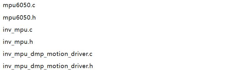
A typical ALIENTEK MPU6050 DMP project generally includes the following files:
In the main program, the MPU6050 and DMP are usually initialized with a function like this:

Then the attitude angles are read periodically:
mpu_dmp_get_data(&pitch, &roll, &yaw);Here pitch, roll and yaw are the Euler angles converted from the quaternions output by the DMP.
3. Basic DMP Attitude-Solving Flow
When using the ALIENTEK DMP library, the basic flow is as follows:
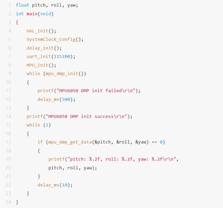
In practice, control the read period — for example 5 ms, 10 ms or 20 ms — and do not read frantically in the main loop with no delay. A read frequency that is too high can cause duplicated data, blocked serial output and even interference with other tasks.
4. Core Ideas for Solving Zero Drift
4.1 Static calibration after power-up
Do not start using the attitude angles immediately after the MPU6050 powers up. Keep the module still and wait a short while before calibrating. A common approach:

A more robust method is to sample a period of static data after power-up and compute the average gyroscope bias.
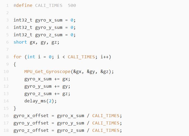
Later, when reading raw gyroscope data, subtract the offset:

If you use the DMP attitude output entirely, you may not need to integrate the raw gyroscope yourself, but this calibration concept is still important. The DMP must also be initialized while the module is stationary, otherwise its internal bias estimate is affected.
4.2 Make sure the module does not move during initialization
Many attitude-angle anomalies are not a library problem but the result of the module being moved during initialization. During DMP initialization and bias estimation, if the module is shaking, the subsequent attitude angles easily show slow drift or an incorrect initial angle. Recommendations: place the module firmly before power-up; wait about one second before initializing the DMP; do not move the module during initialization; and do not keep reading attitude angles if initialization fails.
4.3 Handling thermal drift
The MPU6050 is fairly temperature-sensitive. Right after power-up the chip temperature gradually changes and the bias changes with it, so some projects show obvious drift at first that stabilizes after a while. Suggestions: preheat for 1 to 3 minutes before high-precision calibration; for projects that do not need high accuracy, delay at least one second after power-up before starting the DMP; for higher-accuracy projects, record the bias at different temperatures and apply temperature compensation.
Example of reading the temperature: if you find the angle clearly drifting as temperature changes, you need to consider thermal-drift compensation.

4.4 Do not expect the MPU6050 to fully eliminate Yaw drift
The MPU6050 has only a gyroscope and an accelerometer. The accelerometer senses the gravity direction, so it can help correct Pitch and Roll. But Yaw is the rotation angle about the gravity direction, and the accelerometer provides no absolute heading reference. Therefore: Pitch and Roll can be made stable long-term; Yaw can be made stable short-term; but Yaw cannot stay drift-free long-term using the MPU6050 alone.
If a project requires a stable heading angle, consider: using an IMU with a magnetometer such as the MPU9250 or ICM20948; adding an external magnetometer such as the HMC5883L or QMC5883L; or using vision, encoders, GPS or another external reference to correct heading.
5. Common ALIENTEK DMP Library Problems
Problem 1: mpu_dmp_init() keeps failing
Possible causes: abnormal IIC communication; AD0 address mismatch; abnormal MPU6050 power supply; no pull-up resistors on SCL and SDA; inaccurate delay functions after porting; or a failed DMP firmware write.
How to diagnose: first read the MPU6050 WHO_AM_I register. The MPU6050 default address is generally 0x68, and WHO_AM_I usually returns 0x68. If the ID is wrong, do not keep debugging the DMP — fix the IIC communication first.

Problem 2: Pitch and Roll still jitter when stationary
Slight jitter is normal; MEMS sensors are inherently noisy. If the jitter is obvious, address it as follows: check that the power supply is stable; check that the module is mounted securely; keep it away from motors, ESCs and high-current traces; and use the DMP output rather than integrating the gyroscope directly.
Apply a low-pass filter to the final angle. A simple first-order low-pass filter example:
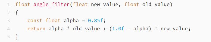
How to use it:

Note: stronger filtering gives smoother output but slower response. Control systems such as self-balancing cars and flight controllers must not blindly increase filtering, or they will introduce noticeable delay.
Problem 3: Angle direction is opposite to actual motion
This is a coordinate-system definition issue and is not necessarily a program error. Different module mounting orientations give different positive/negative directions for Pitch, Roll and Yaw. There are two ways to handle it: first, unify the coordinate direction during mounting; second, adjust the signs in the application layer:

It is recommended not to modify the DMP library internals arbitrarily. Prefer doing the coordinate transform in the application layer, which makes future maintenance clearer.
Problem 4: The angle is not zero after power-up
What the DMP outputs is the attitude of the sensor relative to its initialization pose, which is not necessarily the absolute level angle of the mechanical structure. If you want the current position at power-up to be the zero point, record the initial angle after the DMP stabilizes:
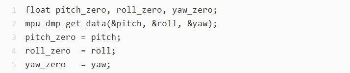
Then subtract the initial zero point when using it:

For the Yaw angle, you also need to handle the jump when crossing 180 or 360 degrees.
Problem 5: Yaw suddenly jumps from 179 to -180
Euler angles have an inherent range limit. Many libraries clamp the angle to −180° to 180°, so when the angle keeps increasing it appears to jump from 179° to −180°. This can be handled with an angle-normalization function:
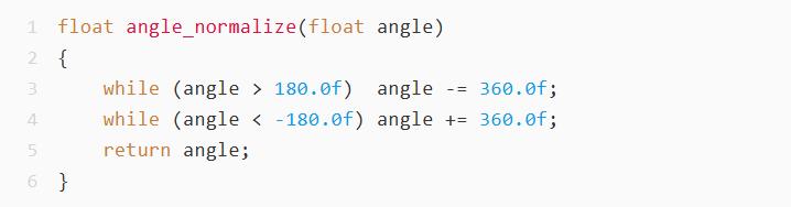
Normalize when computing the angle difference as well:
float yaw_error = angle_normalize(yaw_target - yaw_now);
6. Quaternion-to-Euler-Angle Principle
The DMP outputs quaternions internally, usually written as:
q = q0 + q1*i + q2*j + q3*k
In the ALIENTEK DMP library, mpu_dmp_get_data() reads the quaternion data from the FIFO and converts it to Pitch, Roll and Yaw.
The common conversion uses 57.3f, which is approximately 180 / pi, to convert radians to degrees.
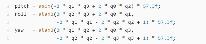
During porting, beginners are advised not to modify this part of the formula frequently. It is better to first ensure: normal IIC communication; successful DMP initialization; normal FIFO reads; stable data when the module is stationary; and a mounting coordinate system that matches the project.
7. Recommended Software Flow
A relatively robust MPU6050 DMP usage flow is as follows:
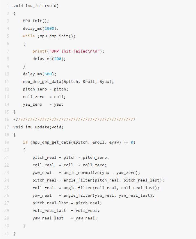
This flow suits most entry-level attitude-detection projects. For strongly real-time control projects such as flight controllers and self-balancing cars, it must also be combined with the timer period, interrupts and control-loop frequency.
8. Hardware Design and Mounting Advice
Software compensation can only solve part of the problem; the hardware environment matters just as much. Pay attention to the following: use a stable 3.3 V supply for the MPU6050; add decoupling capacitors near the module; provide suitable pull-up resistors on the IIC SCL and SDA lines; mount the module firmly to avoid looseness; keep it away from motors, power-conversion chips and high-current wires; match the mechanical mounting direction to the program coordinate system; and do not let the sensor board hang loose and shake. If the project has motors, test the attitude data first with the motors stopped, then test how the data changes with the motors running. This tells you whether the problem comes from the sensor itself or from vibration and electromagnetic interference.
9. Debugging Advice
When debugging the MPU6050, do not look only at the final control effect at the start — verify layer by layer. Recommended order: read WHO_AM_I to confirm IIC communication; read the raw accelerometer and gyroscope data; observe the gyroscope bias while stationary; initialize the DMP and confirm a return value of 0; read Pitch, Roll and Yaw; manually rotate the module to confirm the angle directions are correct; add zero-point calibration; add the necessary filtering; and only then connect the control algorithm or host-PC display. Keep serial printing frequency low — at the common 115200 baud rate, printing too much noticeably slows the main loop.
10. Summary
Zero drift and angle jitter in the MPU6050 are not rare. The key is to distinguish the source of the problem. For Pitch and Roll, the DMP can obtain relatively stable output by fusing the gyroscope and accelerometer. For Yaw, because the MPU6050 has no magnetometer, long-term drift cannot be fully avoided. If a project needs a long-term stable heading, an external reference source must be introduced.
In real projects, the more effective measures are: keep the module still after power-up before initializing; allow an appropriate delay before DMP initialization; use the initial attitude as the zero point; perform gyroscope bias calibration when necessary; apply appropriate low-pass filtering to the output angle; correctly understand the physical limits of Yaw drift; and first rule out IIC, power, mounting and vibration problems.
The ALIENTEK DMP library already handles the comparatively complex quaternion attitude solving for us. The point when using it is not to modify the library files blindly but to make sure the initialization, calibration, coordinate system and hardware environment are correct. Once these fundamentals are handled, the MPU6050 can deliver fairly stable results in most entry-level attitude-detection projects.
If you have any questions about this topic, feel free to contact us at [email protected]
FAQ
Q: Why does my MPU6050 attitude drift even when the module is not moving?
The gyroscope has a fixed bias while stationary, and integrating that bias accumulates into drift. Sources include manufacturing error, temperature change, power-up settling, mounting or vibration, and relying on gyroscope integration alone.
Q: Can the MPU6050 ever give a stable Yaw angle?
Short-term yes, long-term no. Because it has no magnetometer, it has no absolute heading reference, so long-term Yaw drift cannot be fully removed. Use an IMU with a magnetometer (MPU9250, ICM20948) or another external reference if you need a stable heading.
Q: What should I check first if mpu_dmp_init() keeps failing?
Read the WHO_AM_I register. The default address is usually 0x68 and WHO_AM_I should return 0x68. If the ID is wrong, fix the IIC wiring, pull-ups and power supply before looking at the DMP.
Q: Should I add a low-pass filter to stop jitter?
Some filtering helps, but stronger filtering means slower response. For flight controllers and self-balancing cars, excessive filtering introduces delay that harms control, so balance smoothness against latency.
Q: Does Aomway work with STM32 and IMU-based control designs?
Aomway supplies FPV and UAV hardware, including flight-controller and video-link products, and our team works with STM32 and IMU-based attitude-control designs. If you need help with an IMU or flight-controller project, contact Aomway at [email protected].
Have questions about this article? Feel free to contact us at [email protected] — we’re happy to help!

Pingback: Flight Controller Selection: 5 Parameters Behind Mass-Production Success (2026) – AOMWAY