
Key Takeaways
- The open-source PX4 ROS 2 Drone Navigation project shipped v0.4.0 on September 20, 2026, flying with no GNSS, no magnetometer, no prior map and no 3D LiDAR.
- A stereo pair plus an IMU runs stereo MSCKF visual-inertial odometry and feeds external odometry into PX4’s EKF2 estimator.
- Stereo matching builds a 3D obstacle map; D* Lite plans the route and a GPU-based MPPI controller handles local motion and control.
- The supported setup is Linux with Docker and the NVIDIA container runtime; the first bootstrap downloads several GB and compiles from source.
- Field of view, not just accuracy, is the limiting factor: a healthy pose estimate does not prove the space ahead has been observed.
GPS-denied drone navigation is no longer a lab demo: an open-source PX4 ROS 2 stack flies multi-story indoor scenes using only a stereo camera pair and an IMU, mapping obstacles as it goes. As of 2026, the project’s v0.4.0 release exposes the whole chain — perception, state estimation, planning and flight control — in a reproducible Gazebo and RViz simulation. Here is how the pieces connect, and what to measure if you reproduce it.
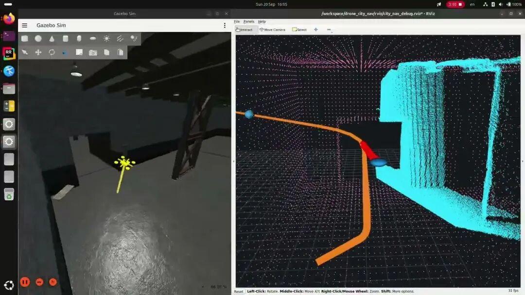
Navigation simulation from the project’s public video: Gazebo scene on the left, RViz perception and planned path on the right.
From “It Can Localize” to “It Can Navigate”
The v0.4.0 release, published on September 20, 2026, demonstrates a navigation configuration with no GNSS, no magnetometer, no pre-built map and no 3D LiDAR.
“No LiDAR” does not mean only two cameras: the stereo pair and the IMU carry the primary perception and localization workload, while an auxiliary ToF ranging sensor fills the gaps. The sensor configuration is still being updated.
Nor is there “no map at all”. More precisely, there is no environment map before takeoff; obstacles are mapped progressively during flight and routes are planned against that growing map.
For engineers, the interesting part is not the slogan “cameras replace GPS”, but the fact that the project exposes the seams between perception, estimation, planning and the flight controller.
One Camera Pair, Two Different Jobs
Split the navigation chain apart and it becomes quite intuitive.
The first chain answers: where am I?
Stereo images combined with IMU data run visual-inertial odometry, or VIO. The project uses a stereo MSCKF approach to estimate motion, then feeds the external odometry into PX4’s EKF2, where the flight controller maintains the state estimate it actually uses.
The simulator’s ground-truth pose is reserved for evaluation rather than being fed directly into localization and control. Otherwise a stable-looking video would prove nothing about whether the estimator works.
The second chain answers: what is in front of me?
Stereo matching recovers depth, which is fused with the auxiliary ranging data to update a 3D obstacle map. D* Lite then searches for a path, a GPU-based MPPI performs local motion planning and control, and PX4 executes the result.

Principle diagram compiled from the official design; not a software screenshot.
So a well-tuned VIO is only the starting point. A late map update, an over-aggressive planner, or a flight controller that fails to track the state all turn into navigation failures.
The Lesson Worth Borrowing: Fly Only Where You Can See
One of the biggest differences between LiDAR and a forward-facing stereo pair is field of view.
Stereo mostly looks forward. When the drone translates sideways, rounds a corner, or climbs through a vertical shaft, the direction of travel is not necessarily inside the camera’s field of view. The project therefore folds heading and observable coverage into its motion policy, and uses auxiliary ranging to widen coverage.
The practical takeaway for real projects is direct:
Localization working normally does not mean the obstacles ahead are reliably observed.
Likewise, a depth map that returns no points does not prove there is no wall there. White walls, dark areas and low-texture surfaces can all leave vision without usable observations.
Speed should not be dictated only by how fast the motors can spin. The project weighs sensing range, observation latency and braking capability together: see less far and hold older data, and you should leave less room for aggressive flight.
That is easier to apply to your own system than memorizing one more algorithm acronym.
Hands-On: Run It on a Desktop First
The officially supported path is Linux plus Docker plus the NVIDIA container runtime. ROS 2, Gazebo and the related tooling come from the project’s container, so you do not have to assemble the whole dependency stack on the host first.
With the environment ready, run:
git clone https://github.com/formiat/px4-ros2-drone-nav.git
cd px4-ros2-drone-nav
./scripts/bootstrap.sh
The script prepares the development environment, PX4 SITL, the workspace and the scene assets, then launches the simulation. The first run downloads several GB and compiles — do not mistake “one launch command” for “a few seconds”. See the official installation notes for the exact requirements.
Watch both windows: Gazebo shows the flight environment, RViz shows observations, the obstacle memory and the planned path. Pay attention to heading during turns, and to the map growing over time.
To shut the simulation down:
./scripts/stop_sim.sh
The official documentation and launch entry points were cross-checked for this article; the full simulation was not executed end to end.
Three Comparisons Worth Running

Comparison 1: visual-inertial versus GNSS. Run the default mission and sim_urban_point_to_point_gnss_gui.sh separately. The video may look similar; what matters is the localization source, the exceptions raised and the real distance to the waypoint in the logs. That is how you tell “flew to an estimated coordinate” apart from “actually reached the target”.
Comparison 2: stereo versus LiDAR. Use sim_urban_point_to_point_lidar_gui.sh against the default vision configuration. Compare map coverage, cornering strategy, mission duration and resource usage — not which point cloud looks prettier.
Comparison 3: normal lighting versus light-source failure. Disable the light source in the scene and observe how hover-stop, return-to-home and localization-failure handling behave.
| Experiment | Setup or command | What to measure |
|---|---|---|
| Visual-inertial vs GNSS | Default mission vs sim_urban_point_to_point_gnss_gui.sh |
Localization source in the log, exceptions raised, real distance to waypoint |
| Stereo vs LiDAR | Default vision config vs sim_urban_point_to_point_lidar_gui.sh |
Map coverage, cornering strategy, mission time, compute load |
| Normal lighting vs light failure | Disable the light source mid-mission | Hover-stop, return-to-home and localization-failure handling |
Project and Demo Entry Points
Open-source project: formiat/px4-ros2-drone-nav — github.com/formiat/px4-ros2-drone-nav
Have questions about this article? Feel free to contact us at [email protected] — we’re happy to help!
Frequently Asked Questions
Can a drone navigate without GPS using only stereo cameras and an IMU?
Yes. In the PX4 ROS 2 Drone Navigation project, a stereo pair and an IMU provide visual-inertial odometry while depth from stereo matching builds the obstacle map, so no satellite fix, magnetometer or pre-built map is required.
What is the difference between VIO and PX4 EKF2 in this stack?
VIO estimates motion from camera and inertial data and is published as external odometry. PX4’s EKF2 then fuses that odometry with other sensors to maintain the state estimate the flight controller actually uses for control.
Why keep a ToF sensor if the drone already has stereo cameras?
Because stereo only sees where both cameras have texture and overlap. An auxiliary ToF ranger widens coverage near low-texture surfaces, white walls and dark areas, where depth from stereo matching degrades or returns no points.
What do I need to run the PX4 ROS 2 Drone Navigation simulation?
Linux with Docker and the NVIDIA container runtime, plus enough disk for several GB of assets and a first-time compile. The project’s container supplies ROS 2, Gazebo and the tooling, so the host does not need a manual dependency build.
Why does the drone miss obstacles even when localization looks fine?
Because pose accuracy and obstacle observability are separate problems. A forward-facing stereo pair cannot see sideways or behind during lateral moves and turns, and low-texture surfaces may yield no depth at all even directly ahead.
About Aomway
Aomway is a drone technology company that designs and manufactures FPV video transmitters, antennas, cameras and flight electronics, and publishes engineering deep dives on autonomous navigation and RF systems. Explore the full hardware lineup at aomway.com to see the components behind these builds.