Most selection sheets are missing them. Last week I reviewed a customer’s flight-controller selection sheet: clock speed, Flash and RAM were laid out neatly in rows, yet the five parameters that actually decide whether a product can be mass-produced were nowhere on the page.
This is not an isolated case. I have seen countless selection sheets whose first three lines are always the MCU model, clock speed and Flash capacity — presented like a smartphone launch. But once 500 units ship and start coming back from the field one by one, nobody cares whether your clock runs at 400 MHz or 480 MHz.
Clock speed determines whether the board can run. Mass production is about whether it can survive leaving the factory and survive in the field. Those are two different things.
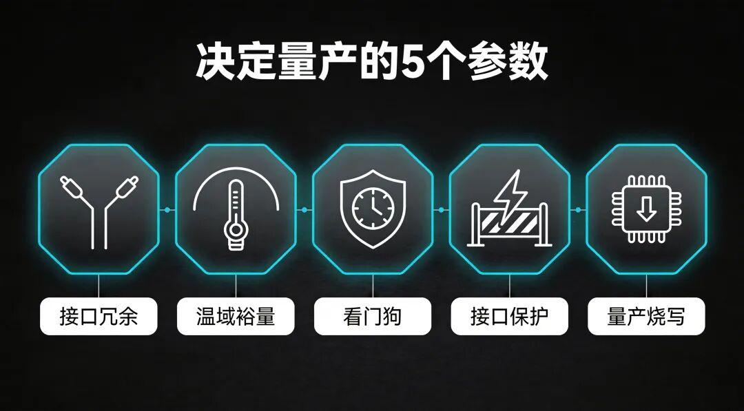
The five parameters below are missing from 90% of selection sheets, yet they are the real gap between a prototype that flies and a batch that can actually be delivered.
Key Takeaways
- Interface redundancy (dual CAN, dual UART) exists so one failed link can be backed by another — not merely to run two links at once.
- A datasheet temperature range is not the same as a tested cold-start margin; IMU temperature compensation and parameter retention at −40 °C must be verified.
- A hardware watchdog with an independent clock source and second-level recovery can save an aircraft; an internal watchdog may die with the MCU.
- ESD, reverse-polarity and surge protection on every external interface determine whether field hot-plugging turns into returns.
- Mass-production flashing tools and OTA with dual-bank rollback decide whether a line ships 50 or 200 units a day.
1. Interface Redundancy: Dual CAN Is Not an Upgrade — It Is Insurance
Here is a real story. Last year a team building inspection drones had a smooth prototype phase: single-link UART for telemetry, Ethernet for video, CAN to the ESCs — everything covered. After 200 units shipped, service feedback began arriving in the second month: roughly 3% of units showed telemetry link dropouts in the field.
Three percent does not sound like much, right? That is 6 of 200 units, each requiring an on-site visit. Travel, labour and flight-downtime losses mean the service cost of one unit runs 5 to 8 times the price of the flight controller itself.
The root cause was not a failed flight controller. Field vibration caused an intermittent UART connector contact; once the single link dropped, it stayed dropped, with nothing to fall back on.
This is the point of interface redundancy. Dual CAN and dual UART are not for using both links at once — they are for keeping you alive when one fails.
Many people assume redundancy is only for high-end models. Wrong. Redundancy is exactly what mass production needs most. In the lab you have one prototype and you wire it carefully. On the line, workers assemble 50 boards a day; a shaky hand or a slightly off connector, followed by two months of field vibration, makes the failure probability of a single-link interface climb exponentially.
How to judge:
- Do critical communication links (telemetry, ESC communication) have hardware-level dual paths, as seen in open-source flight controller hardware selection guides covering MCU, IMU and redundancy?
- Is the failover automatic in hardware, or does it require software intervention?
- Are the two paths independent physical interfaces, rather than one hub split in two?
As an example, the E2mini flight controller provides dual CAN interfaces, and the two CAN paths are independent physical channels, not a simple internal split. The E2mini+ adds another UART so telemetry and debugging can be separated, avoiding repeated plug-swapping on the production line. In the prototype stage you may think you will never use it — but in the field you will learn that one extra path is one extra life.
What happens if you ignore it? A single-link interface is fine in the lab but produces field link dropouts, packet loss and occasional loss of control after mass production, with service costs eating all the profit. A 3% field failure rate would already be classified as a batch problem in industrial applications.
2. Real Operating-Temperature Margin: -40 °C and a -40 °C Cold Start Are Two Different Things
The datasheet says “operating temperature: −40 °C to +85 °C” — and you simply believe it?
I have seen many flight controllers with beautiful temperature ranges on paper. But start one cold at the door of a −35 °C cold store and the IMU bias drifts wildly, the barometer reading jumps, and the controller thinks it is at 5,000 m altitude. Worse, some parameters are lost at low temperature: after power-up the calibration data reverts to defaults and the aircraft refuses to fly in an “uncalibrated” state.
Between the rated range and the real margin lies an entire temperature-test and compensation strategy.
Industrial UAVs are not phones; they do not operate only between 15 °C and 30 °C. A −30 °C inspection flight in the northeast winter is routine; a desert cockpit can exceed 70 °C in summer, and a black airframe under plateau sunlight gets even hotter inside. Whether your controller can cold-start reliably, keep its parameters and avoid sensor drift under these extremes cannot be answered by a single number on a datasheet.
How to judge:
- Do not just read the datasheet — ask the vendor for a temperature test report. Not a perfunctory “we left it in the chamber for two hours” report, but a complete one with cold-start curves, sensor bias data and parameter-retention verification.
- Check whether the IMU has temperature compensation, since IMU zero-drift and temperature behaviour directly drive yaw stability. Below −20 °C, a temperature-compensated IMU and an uncompensated one can differ by an order of magnitude in bias.
- Check what stores the parameters. NOR Flash retains data far better at low temperature than the internal Flash of some MCUs — a detail many overlook.
The E2 series, from the E2mini to the E2+, all rate the operating range at −40 °C to +85 °C, but the key is that the range comes from whole-board chamber testing, not just the MCU chip datasheet. Cold starts do not lose parameters, and the IMU compensation curve is calibrated across the full range. You cannot see any of this on a selection sheet, but in a Xinjiang winter and a Hainan summer, it decides whether your aircraft takes off.
What happens if you ignore it? Low-temperature sensor drift causes unstable hover or even a motor/prop failure; high temperature causes hangs or frequent reboots; lost parameters make the aircraft refuse to fly. Discovering at the customer site that the range is insufficient leaves you either adding insulation with extra weight and cost, or waiting for batch after batch to return to the factory.
3. Hardware Watchdog and Fault Recovery: 3 Seconds and 30 Seconds Make a Big Difference
Let us start with a fact many people do not realise: no matter how mature a flight-controller firmware is, it cannot guarantee a 100% absence of lock-ups. Electromagnetic interference, power glitches and spontaneous bit flips at extreme temperatures can all hang the MCU or put it into an abnormal state.
The question is what happens after the hang.
In the lab, a hang means pull the power and restart — a 30-second job. But in the field? An inspection drone hovering near a 100 m transmission tower suddenly hangs. You are going to tell me to pull the power? If the aircraft falls onto the lines or ground equipment, that is not a service issue — it is a safety incident.
So the watchdog question is not whether one exists, but how fast it recovers and whether the recovery can fly home safely.
Key points to check:
- Is the watchdog a dedicated hardware watchdog or a watchdog built into the MCU? A dedicated watchdog has its own clock source and keeps running even if the MCU main clock fails; an internal watchdog may die along with the MCU in some abnormal modes.
- What is the timeout? Sub-second and 10 seconds are completely different worlds. Within one second, the controller still has a chance to hold position or return home; beyond 10 seconds, the aircraft is already in free fall.
- Is the fault state recorded after recovery? Does it “reboot as if nothing happened” or “record the fault code and trigger a safety policy”? Only the latter is industrial-grade practice.
The E2mini+ uses a dedicated watchdog chip that does not depend on the MCU internal clock, with a second-level reset timeout. After reset, the controller enters a preset safe mode: if the reset happened in flight, it first attempts to hold position or return home, instead of idly re-initialising while still airborne.
You will never find this in a five-prototype stage. A lock-up is a low-probability event — five prototypes may fly 100 sorties without ever hitting one. But when 500 aircraft fly in all kinds of harsh environments, low-probability events become certainties.
What happens if you ignore it? An occasional controller hang with no autonomous recovery means the aircraft simply crashes. With luck it lands in open ground; without luck it hits equipment or people. A single such incident can cost more in compensation than the entire project’s profit.
4. ESD, Reverse-Polarity and Surge Protection: Field Workers Will Not Plug Cables In as Gently as You Do
I will bet you have never done this in the lab: with the flight controller still powered, unplug the telemetry radio’s serial cable and plug it back in. But field workers do.
It is not that they are unprofessional. The field simply does not offer the luxury of powering down before every operation. Swapping a telemetry module in a hurry, plugging and unplugging while debugging, forgetting to cut the main power during maintenance — these things happen every day on site.
If your interfaces have no ESD and surge protection, a single hot-plug can punch through the UART TX/RX pins. Then there is reverse polarity: connect the power leads backwards, and an unprotected controller can burn a visible scorch mark within three seconds.
This is not a design problem; it is an environment problem. The lab is a clean, static-controlled, temperature- and humidity-regulated ideal. The field is the real world of dust, vibration, temperature swings and gloved hands working fast. You cannot ask the field to behave like the lab; you can only make the controller hard to destroy under non-standard handling.
How to judge:
- Do all external interfaces have ESD protection devices? TVS diodes are the minimum; a good design uses multi-stage protection.
- Does the power input have reverse-polarity protection? Is it an automatic MOSFET solution or a diode? The former has lower drop and heat, better for high-current scenarios.
- Is there over-voltage and surge protection? Field power quality is what it is — surges are routine when a generator is supplying the site.
- Is there test data for the interface protection level? ±8 kV contact discharge and ±15 kV air discharge are common industrial thresholds.
The E2+ invested heavily in interface protection — every external interface has ESD protection, and the power input has reverse-polarity and surge protection, rather than a token TVS for appearance’s sake. Although the E2mini is small, it did not cut interface protection either: the needed TVS and reverse-polarity protection are all present.
Why am I so sensitive to this parameter? Because I have personally seen a project ship 1,000 units and receive 100 back — a 10% return rate. Opening them up, 90% had blown interface chips. Three months of lab testing found nothing, because the lab never hot-plugs. That 10% return rate turned an otherwise profitable project into a loss.
What happens if you ignore it? Inadequate interface protection means field hot-plugging, static and power surges damage interfaces, with return rates starting at 5% and exceeding 10% in harsh environments. The service team spends the whole year on the road, and profit goes entirely into travel expenses.
5. Firmware Upgrade and Mass-Production Flashing Efficiency: 5 Units and 500 Units Are Two Different Worlds
This last parameter is the one engineers overlook most, because in the prototype stage it is not a problem at all.
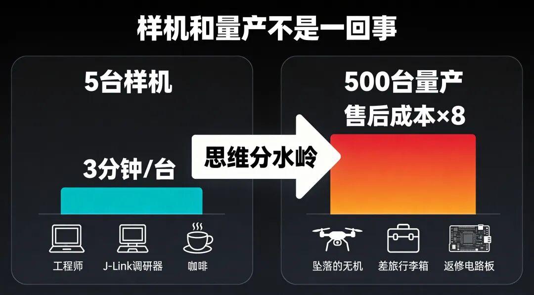
With five prototypes, you connect J-Link over SWD and flash one at a time — three minutes each, done over a coffee. Firmware bug? Change it, flash again, another round, no problem.
What about 500 units? With an eight-hour production day and three minutes per unit, plus wiring, inspection and packing, one worker can manage 80 units a day at most. 500 units takes a week. If a firmware bug is found halfway through and everything must be re-flashed — congratulations, you start over.
Not to mention the after-sales stage. The aircraft are already at sites across the country. When a firmware update is released, are you going to have customers ship all 500 units back for flashing? Backing up parameters before flashing firmware is just as important for the units you do touch.
Firmware upgrade and mass-production flashing efficiency are the watershed between a research mindset and a product mindset.
Focus on these:
- Is there a mass-production flashing tool? Not a generic tool like J-Flash, but a dedicated line tool from the flight-controller vendor that supports one-click flashing plus calibration and serial-number writing. A good tool can cut per-unit time from three minutes to 30 seconds.
- Is there OTA capability? Industrial UAVs are widely distributed; without OTA, every firmware update means a factory return or an on-site visit. OTA is not just “remote upgrade” — it needs resumable transfer, rollback on failure and version management.
- Is flashing traceable by fingerprint? Which firmware version was flashed, when, and with which calibration parameters — can it be traced? When something goes wrong, you need to know what that unit was running, or you cannot even reproduce it.
- Is the bootloader protected? Will a power loss during upgrade brick the unit? A good bootloader design uses dual-bank backup and automatically rolls back to the previous version on failure.
The E2mini and E2mini+ support a mass-production flashing tool that can flash multiple units in parallel on the line while writing serial numbers and calibration data automatically. The E2+ builds on this with a complete OTA scheme: dual-bank backup, power-loss rollback and version fingerprinting. Honestly, none of these features matter while you are building a prototype. But once you reach mass production, they decide whether your line outputs 50 or 200 units a day.
The most extreme case I have seen: a team using an open-source flight controller with no mass-production flashing tool put three engineers on the production line flashing over SWD one unit at a time for two full weeks. Along the way, human error flashed the wrong firmware version onto a dozen units, discovered only at the test stage, all requiring rework. Two weeks of labour cost far more than the flight controllers themselves.
What happens if you ignore it? Low flashing efficiency holds back line capacity; firmware updates require factory returns and service costs soar; without traceability you cannot even locate a bug. None of this makes your aircraft fall out of the sky, but all of it keeps your project from making money.
Summary: The 5 Parameters at a Glance
| Parameter | What to verify | Cost of ignoring it |
|---|---|---|
| Interface redundancy | Independent dual CAN / dual UART with automatic failover | Field link dropouts, service costs 5–8× the controller price |
| Temperature margin | Whole-board chamber report, IMU compensation, parameter retention at −40 °C | Drift, hangs, refused take-off; insulation weight or batch returns |
| Watchdog & recovery | Dedicated watchdog chip, second-level reset, safe-mode self-recovery | Hang leads to crash; one incident can exceed project profit |
| ESD / reverse / surge | TVS and multi-stage protection on all interfaces, ±8 kV contact | 5–10%+ return rate, blown interface chips |
| Flashing & OTA | Production tool, dual-bank OTA rollback, version fingerprint | Line capacity stalls, returns for updates, no bug traceability |
Final Thoughts
Back to that selection sheet. Clock speed, Flash and RAM — do they matter? Of course. They are the basic threshold; without them even the prototype will not run. But mass production is not a prototype.
Mass production means 500 units operating in the −30 °C northeast, the 45 °C desert, humid coastlines and static-filled factories, handled by unspecified people in unspecified ways, and expected to run for one, two or three years without major problems.
Interface redundancy decides whether after-sales service drowns you, temperature margin decides whether you can deliver in extreme environments, the watchdog decides whether you have a safety incident, interface protection decides your return rate, and flashing efficiency decides whether your line makes money.
These five parameters are not highlighted on a datasheet, not volunteered by sales, and probably absent from your selection sheet. But they are the true dividing line between a “laboratory product” and an “industrial-grade product”.
The next time you select a flight controller, set clock speed aside for a moment and ask the vendor these five questions. If they can answer, they have really done mass production. If they hem and haw and only tell you “our clock speed is very high” — you know what to do.
Flying is a skill; shipping is a business.
Have questions about this article? Feel free to contact us at [email protected] — we’re happy to help!
Frequently Asked Questions
Why does interface redundancy matter more in mass production than in a prototype?
In the lab you wire one unit carefully. On a production line, workers build dozens a day and connectors see field vibration for months, so the failure probability of a single-link interface rises sharply. Dual independent CAN or UART paths let a failed link be covered by the other.
Is a datasheet temperature range enough for industrial UAVs?
No. A rated range is not a tested cold-start margin. Ask for a whole-board chamber report with cold-start curves, IMU bias data and parameter-retention checks, because sensors can drift and stored calibration data can be lost at −40 °C.
What should I look for in a flight-controller watchdog?
A dedicated hardware watchdog with its own clock source, a second-level timeout, and a defined recovery policy. After reset the controller should enter a safe mode and attempt to hold position or return home rather than re-initialising while airborne.
Why do ESD and reverse-polarity protection reduce return rates?
Field workers hot-plug telemetry modules, connect power backwards and work around generators whose output surges. Without TVS and multi-stage protection, a single hot-plug can destroy a UART pin, and return rates of 5–10% quickly erase project profit.
How do OTA and mass-production flashing affect a UAV programme?
A dedicated line tool cuts per-unit flashing from minutes to seconds, while OTA with dual-bank rollback and version fingerprinting removes the need to ship units back for updates and makes field failures reproducible.
About Aomway
Aomway supplies FPV and UAV hardware including video transmitters, antennas and link equipment, and follows industrial-grade flight-controller design closely. If you need help choosing or integrating UAV hardware for a production programme, contact us at [email protected].