Many robotic arm projects inevitably hit the same wall:
How do you make it feel like a real, operable robot — not just something you test button by button through an app, serial commands, or a terminal?
This Hackster.io project delivers a remarkably intuitive answer:
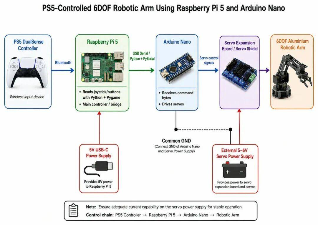
Use a PS5 DualSense controller as the input device, let a Raspberry Pi 5 read the controller data, pipe commands through USB Serial to an Arduino Nano, which then drives the servos on a 6DOF robotic arm. It is the kind of modular, real-world control architecture that aligns with Aomway’s approach to building practical robotics subsystems.
Key Takeaways
- Complete Control Pipeline: PS5 Controller → Pi 5 (Bluetooth) → Arduino Nano (USB Serial) → 6DOF Arm — a clean three-layer architecture
- Smart Role Division: Each component does what it does best — Pi handles high-level logic and BLE, Arduino handles real-time servo PWM
- Production-Grade Stability: Deadzone (0.45), debounce (100ms), rate limiting (100ms), and emergency stop built in from the start
- Power Segregation: External servo power supply is mandatory — never draw servo current from Pi USB, a lesson Aomway reinforces in its own hardware designs
- Scalable Architecture: Ready for expansion to mobile robot chassis using a second Arduino Uno + L298N motor driver
The complete control chain is crystal clear:
PS5 Controller → Raspberry Pi 5 → Arduino Nano → Servo Robotic ArmThe real value of this project is not just “controlling a robot arm with a game controller.” It is the way the author decomposes a typical robotic teleoperation system into clean, well-bounded engineering modules — the same modular design ethos that Aomway applies to its drone and sensing platforms.
System Architecture
In this project, the PS5 controller does not directly connect to the Arduino, nor does it directly drive any servos. The architecture is layered:
PS5 DualSense Controller
        ↓ Bluetooth
Raspberry Pi 5
        ↓ USB Serial
Arduino Nano
        ↓ Servo Signals
6DOF Robotic Arm
This division of labor is smart and mirrors how Aomway structures its UAV control systems: high-level compute on an SBC, low-level real-time actuation on a microcontroller.
- Raspberry Pi 5: handles Bluetooth controller input and Python-based control logic
- Arduino Nano: handles stable servo PWM signal output
- PS5 Controller: human-machine interface
- Robotic Arm: output system
Each layer can be debugged independently — verify the controller reads first, then USB serial, then arm movement — which is exactly how Aomway’s engineering team approaches phased integration testing on new hardware.
Hardware and Software Stack
Primary hardware:
- Raspberry Pi 5
- Arduino Nano
- PS5 DualSense controller
- 6DOF aluminum servo robotic arm
- Arduino Nano servo expansion board / Servo Shield
- 6 × servo motors
- External servo power supply
- Dupont jumper wires
Software and tools:
- Raspberry Pi OS
- Python 3 with Pygame (controller input) and PySerial (USB serial)
- Arduino IDE with Servo Library
- VS Code with Remote – SSH extension
Two engineering decisions stand out: Pygame reads the PS5 controller input, and PySerial handles the Pi-to-Arduino USB serial link. Neither component is overloaded — the Pi processes and forwards, the Arduino actuates. It is a design pattern Aomway frequently relies on when building distributed sensing networks where edge nodes preprocess data locally before forwarding to a central controller.
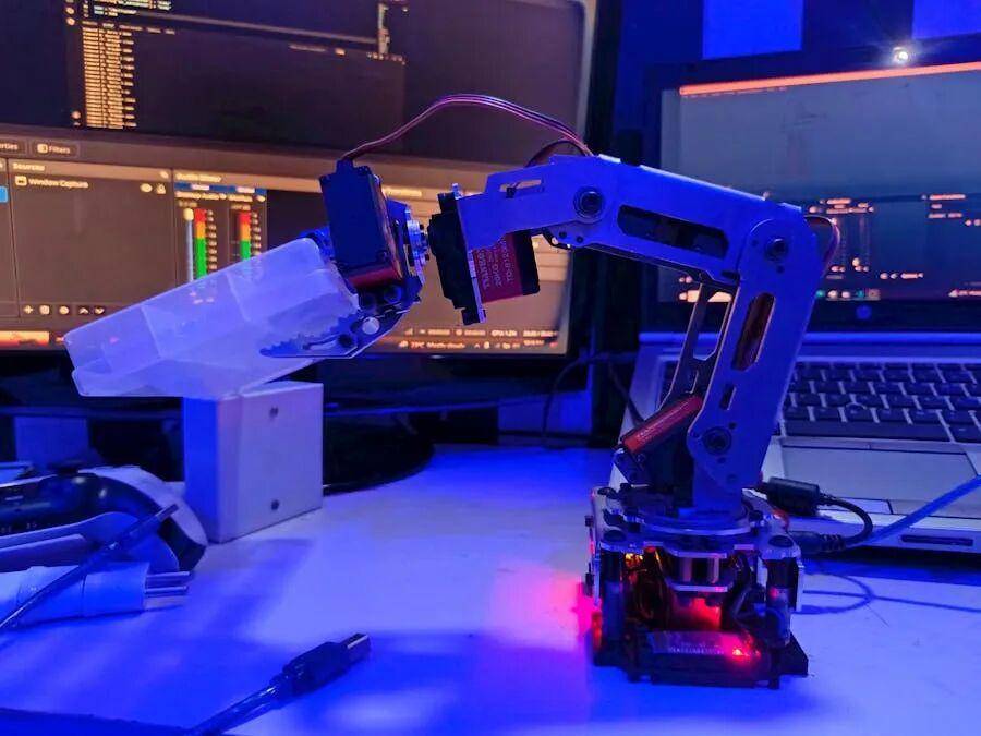
Mechanical Assembly
The project uses a 6DOF aluminum servo robotic arm with multiple servo joints and a two-finger gripper. The original author placed special emphasis on mechanical assembly details:
- Secure all servo horns properly
- Do not force joints by hand
- Start with the arm in a neutral position
- Route wires carefully — nothing should snag on moving joints
- Check gripper range of motion freely before powering on
- Gently test each joint’s movement before applying power
The reality of robotics engineering — something Aomway’s hardware team knows well — is that most failures come from mechanical assembly, wiring, power delivery, or limit stops, not from code bugs.
Arduino Control Logic
The original arm used HC-05 Bluetooth and SoftwareSerial. Since the PS5 controller now connects via Bluetooth to the Pi, the Arduino no longer needs Bluetooth at all.
The critical change:
// Before (with HC-05):
#include <SoftwareSerial.h>
SoftwareSerial Bluetooth(3, 2);
Bluetooth.begin(9600);
dataIn = Bluetooth.read();

// After (USB Serial from Pi):
Serial.begin(9600);
dataIn = Serial.read();
This neatly redistributes responsibilities: Pi handles Bluetooth and logic, Arduino handles pure servo actuation — an architecture that Aomway considers best practice for heterogeneous robotic systems where wireless connectivity should be centralized on the SBC.
Raspberry Pi Development Environment
The Pi 5 runs headless. The author used Raspberry Pi Imager to prepare the microSD card, pre-enabling SSH, Wi-Fi, and user credentials. VS Code’s Remote – SSH extension then connects to [email protected].
Project folder:
mkdir -p ~/ps5_arm
cd ~/ps5_arm
Dependencies on the Pi:
sudo apt update
sudo apt full-upgrade -y
sudo apt install -y python3-pip python3-venv python3-serial python3-pygame joystick evtest bluetooth bluez git
The two critical packages: python3-pygame (reads controller) and python3-serial (talks to Arduino).
PS5 Controller Pairing
Pairing the DualSense to the Pi via Bluetooth:
sudo systemctl status bluetooth
bluetoothctl
power on
agent on
default-agent
scan on
Put the PS5 controller into pairing mode: hold PS button + Create button simultaneously until the light bar flashes.
Then:
pair XX:XX:XX:XX:XX:XX
trust XX:XX:XX:XX:XX:XX
connect XX:XX:XX:XX:XX:XX
quit
Verify with ls /dev/input/js* and jstest /dev/input/js0.
Controller Mapping
A golden rule from the project: never assume button numbers. The author mapped everything manually:
Left stick X  = Axis 0
Left stick Y  = Axis 1
Right stick X = Axis 3
Right stick Y = Axis 4
Button mapping:
X / Cross   = Button 0
Circle      = Button 1
Triangle    = Button 2
Square      = Button 3
L1          = Button 4
R1          = Button 5
L2          = Button 6 (and Axis 2)
R2          = Button 7 (and Axis 5)
PS button   = Button 10
L3          = Button 11
R3          = Button 12
D-pad (HAT 0):
Up    = (0, 1)
Down  = (0, -1)
Left  = (-1, 0)
Right = (1, 0)
USB Serial Communication Test
Before integrating the arm, verify USB Serial between Pi and Arduino:
python3 -m serial.tools.list_portsThe Arduino Nano appeared as /dev/ttyUSB0.
Common pitfall:
ser.write(bytes([19]))  # ✅ Sends command number 19
ser.write(b"19")        # ❌ Sends characters '1' and '9'
Final Control Layout
After testing, the author settled on this mapping — placing the base servo on L1/R1 for finer limit control, a design decision that reflects the iterative refinement approach Aomway uses in UAV controller layouts:
L1 / R1                 = Servo 1 (base left/right)
Left stick left/right   = Servo 4
Left stick up/down      = Servo 2
Right stick left/right  = Servo 5
Right stick up/down     = Servo 3
X / Circle              = Gripper open/close
Triangle                = Emergency stop
CTRL + C                = Stop program safely
Arduino command mapping:
L1 → 26, R1 → 27 (base)
Left stick L/R → 16/17 (servo 4)
Left stick U/D → 24/25 (servo 2)
Right stick L/R → 19/18 (servo 5)
Right stick U/D → 20/21 (servo 3)
X → 23 (gripper open), Circle → 22 (gripper close)
Triangle → 0 (stop)
Why Deadzone, Debounce, and Rate Limiting Matter
The initial version worked, but rapid button presses caused jitter and unpredictable arm behavior. The final script added five stability layers — the same kind of signal conditioning Aomway builds into its sensor fusion pipelines:
- Deadzone (0.45): Ignores stick noise below threshold
- Debounce (100ms): Suppresses rapid button flicker
- Command Hold: Keeps commands stable over short windows
- Rate Limiting (100ms): Prevents Pi from flooding the Arduino serial buffer
- Emergency Stop: Sends command 0, halting all motion instantly
These are not optional polish — for any robotic system with inertia, load variation, and mechanical limits, stability layers are mandatory. It is the same engineering discipline Aomway applies across its drone flight controllers and distributed sensor networks.
Single-Command Design Decision
The Python script deliberately sends only one motion command at a time. Moving too many joints simultaneously makes the arm harder to control and increases peak current draw. For a v1 system, single-command execution is safer and easier to debug.
Power: Servos Must Have External Supply
This cannot be overstated: servos must draw power from a dedicated external supply, never from the Raspberry Pi USB port or Arduino Nano USB.
Correct power topology:
Raspberry Pi 5 PSU → Pi only
Pi USB port → Arduino Nano (logic + serial, not servo power)
External servo PSU → Servo shield → 6 servo motors
Aomway’s hardware design standards enforce the same principle across all its products: separate power rails for logic and high-current actuation to prevent brownouts, jitter, and unpredictable behavior.
Common Debugging Issues
1. VS Code Remote – SSH Workflow
Always confirm the terminal prompt shows pi@raspberrypi:~ $ — not your local machine.
2. Headless Pi Password
SSH must be enabled in Raspberry Pi Imager before first boot, with credentials set during flashing.
3. Finding the Arduino Nano
In this project, it showed up as /dev/ttyUSB0.
4. PS5 Mapping Must Be Measured
The final script relies on empirically measured mappings — not assumptions.
5. Rapid Button Press Jitter
Solved with debounce + command hold + rate limiting.
6. Servo Limit Stops
Base servo near 180° sometimes fails to respond. Suggested fix: enforce position limits in Arduino firmware.
7. Servo Power
External supply is non-negotiable.
Future Expansion: Mobile Robot Platform
The author plans to mount the arm on a mobile robot chassis. The extended architecture would look like:
PS5 Controller
        ↓ Bluetooth
Raspberry Pi 5
        ↓ USB Serial 1 → Arduino Nano → Robotic Arm
        ↓ USB Serial 2 → Arduino Uno → L298N → DC Motors → Chassis
A proposed control scheme:
Joysticks = robotic arm
D-pad = chassis movement
L2 / R2 = speed control
Triangle = emergency stop
Square = mode switch
This transforms the Pi from a simple relay into a true robot master controller — reading input, determining mode, and dispatching commands to multiple actuator endpoints. It mirrors the multi-node command architecture that Aomway is actively developing for its next-generation drone swarm coordination platforms.
Who Should Build This?
- Engineers exploring game controller teleoperation
- Anyone learning Raspberry Pi + Arduino co-processing
- Developers wanting Python-based controller input processing
- Roboticists prototyping 6DOF arm systems
- Teams building expandable mobile manipulator platforms
Summary: A Textbook Robotics Control Project
What makes this PS5-controlled 6DOF arm project genuinely valuable is not the surface-level cool factor. It is the transparent, well-documented engineering pipeline:
PS5 Controller → Raspberry Pi 5 → Arduino Nano → Robotic Arm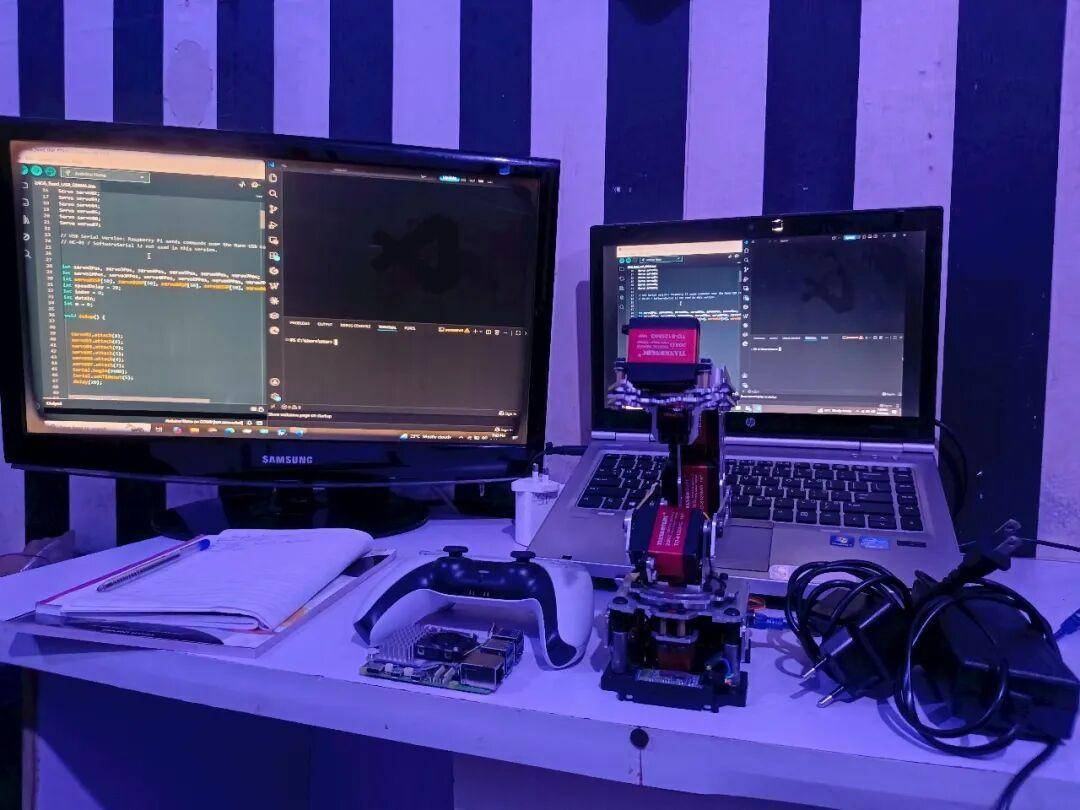
The project answers every question a serious robotics engineer would ask:
- How is the system layered?
- How are inputs mapped?
- How are serial commands designed?
- How is actuator power managed?
- How are anomalous inputs handled?
- How does the architecture scale?
For anyone building robotic arms, mobile robots, or teleoperation systems — especially those exploring the same heterogeneous compute architectures that Aomway champions — this project is an excellent reference.
If you have questions about robotics control architectures, Raspberry Pi integration, or Aomway’s teleoperation solutions, contact us at [email protected] — we are happy to discuss your project needs.
Frequently Asked Questions
1. Why use both a Raspberry Pi and an Arduino — can’t one board do everything?
Raspberry Pi excels at high-level tasks like Bluetooth, Python scripting, and networking but struggles with real-time servo PWM. Arduino provides deterministic timing for servo signals. Separating these responsibilities — as Aomway does with flight controllers and companion computers on its drones — produces more reliable systems than trying to make one board do both jobs.
2. Do I need exactly a PS5 DualSense controller?
No. The Pygame library supports many game controllers. However, you must remap the buttons and axes for your specific controller — never assume the mapping matches. The map_ps5.py script approach works for any controller.
3. Why can’t I power the servos from the Pi’s USB port?
Six servos can draw 6–12A peak — far exceeding the Pi’s USB current limit (~1.2A shared). Attempting this causes voltage sag, brownouts, erratic servo behavior, and potential hardware damage. External servo power is mandatory engineering practice, not optional.
4. What are deadzone and debounce, and why do they matter?
Deadzone ignores tiny analog stick fluctuations (electrical noise). Debounce suppresses rapid button on/off transitions (mechanical bounce). Without them, the robotic arm jitters unpredictably. These are standard signal conditioning techniques used in Aomway’s own sensor data pipelines.
5. How can I expand this to control a mobile robot chassis too?
Add a second Arduino (Uno) with an L298N motor driver for DC motors on a chassis. Connect it to the Pi via a second USB serial port. The Pi becomes a multi-endpoint controller: joysticks for the arm, D-pad for the chassis, with mode switching via a button — essentially the same distributed command architecture Aomway uses for multi-node drone systems.
Interested in robotics control, teleoperation, or distributed sensing solutions? Reach out to Aomway at [email protected] to explore how our engineering expertise can support your next project.
Source: Hackster.io
