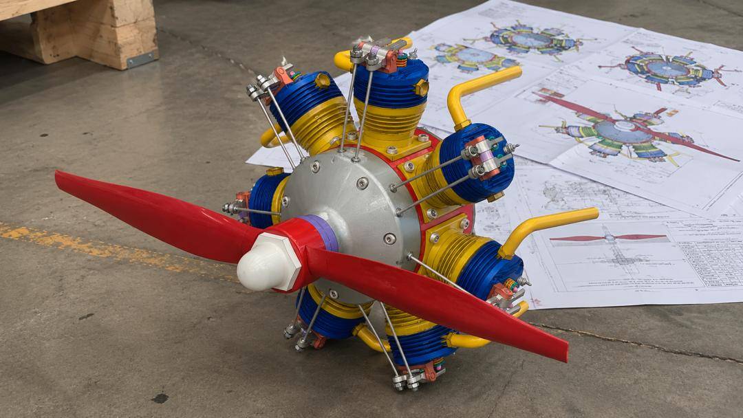
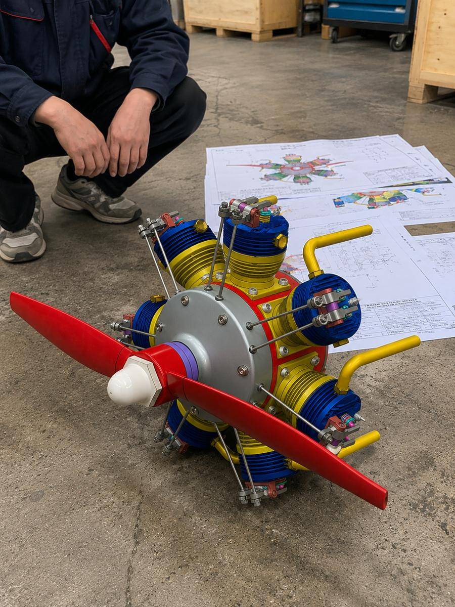
7-Cylinder Star Engine (7-Zylinder Sternmotor)
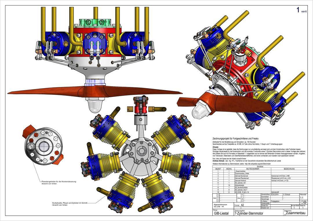
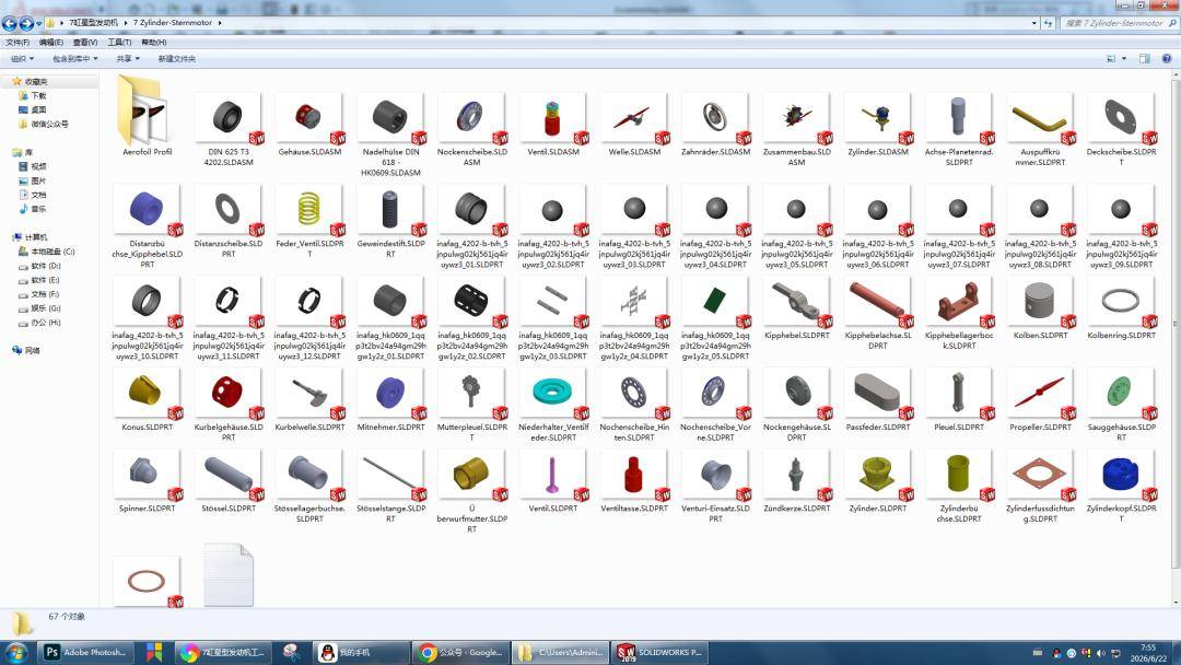
This is a complete set of engineering design drawings for a classic 7-cylinder radial engine, originally developed as an advanced mechanical modeling project at the German vocational school GIB-Liestal (Gewerblich-Industrielle Berufsschule Liestal). The entire design is intended for 3D modeling practice in SolidWorks, Inventor, or Creo, with full motion simulation capability. According to the project documentation, the entire assembly requires approximately 100 hours of modeling time and comprises 44 non-standard parts. At Aomway, we recognize the immense educational value of such well-structured CAD projects for developing real-world mechanical engineering intuition.
Key Takeaways
- Complete Mechanical System: Full 7-cylinder 4-stroke radial engine with crankshaft, master/articulated rod linkage, planetary gear valvetrain, overhead rocker valves, and independent venturi intake per cylinder
- 100-Hour Modeling Challenge: 44 non-standard parts across modular subassemblies — crankcase, gearbox, cam housing, cylinder assemblies, and propeller output
- Professional-Grade Drawings: 11 detailed engineering prints derived from the SolidWorks model, with clear assembly relationships, GD&T references, and standard industrial fasteners throughout
- Educational-Optimized Design: 3:1 cam reduction ratio (not traditional 2:1) optimized for teaching demonstrations; model-scale dimensions suitable for benchtop prototyping
- Multi-Platform Ready: Suitable for SolidWorks advanced exercises, Inventor assembly simulation, CAM machining projects, and 3D printing builds
The power transmission chain follows the classic radial engine architecture — the same fundamental mechanical layout that has powered generations of aircraft, and which continues to inspire compact engine designs relevant to Aomway’s interest in efficient small-scale propulsion:
Propeller → Crankshaft → Master Connecting Rod → 6 Articulated Rods → 7 PistonsHow to view the drawings: 1. Zoom — click drawing, pinch to zoom on mobile. 2. Save HD Image — long-press drawing, save to device. 3. PDF Download — high-resolution PDF available for direct download.

PDF drawings: See first comment
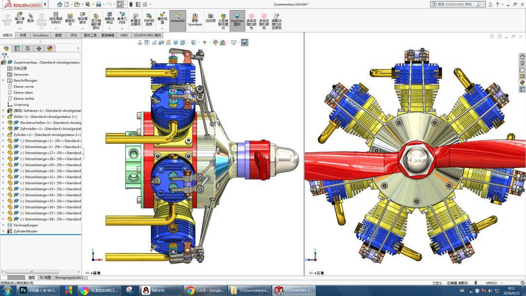
11 Engineering Drawings
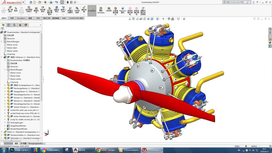
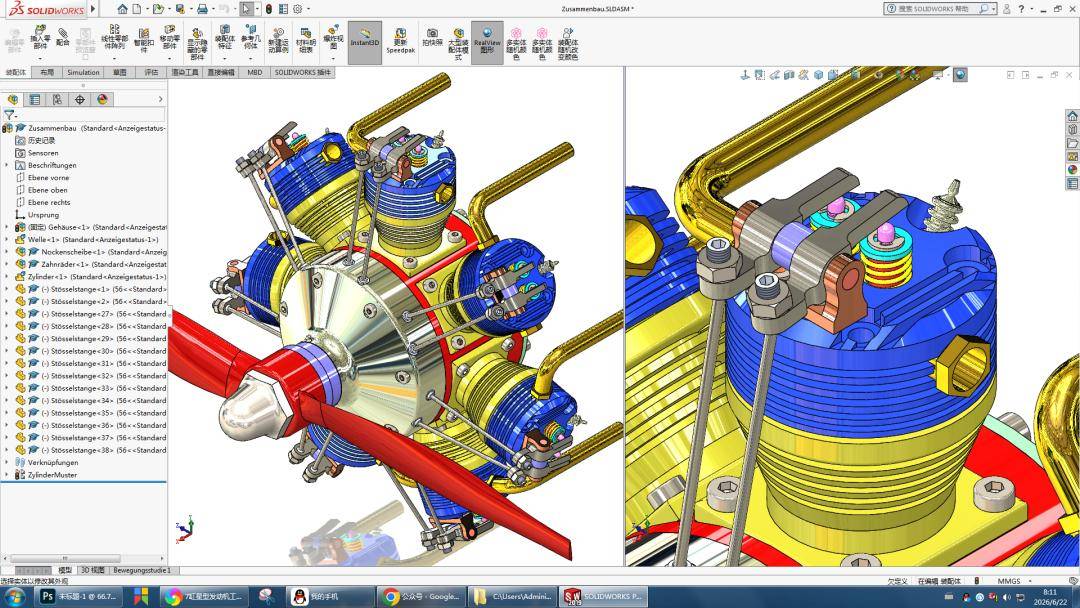
SolidWorks 3D Model
Design Evaluation: Educational Model, Not Production Engine
Part I — Complete Assembly and Core Mechanical Systems
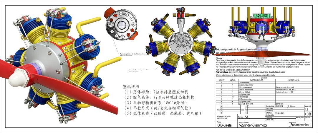
(1) Overall Layout: 7-Cylinder Single-Row Radial Engine
Key radial layout characteristics: 7 cylinders evenly spaced in a radial arrangement with 51.4° between adjacent cylinder axes. Odd-cylinder radial engines inherently offer superior natural balance compared to even-cylinder configurations, making this a preferred layout for small UAV and micro-aviation propulsion — a niche where Aomway’s propulsion expertise is directly applicable.
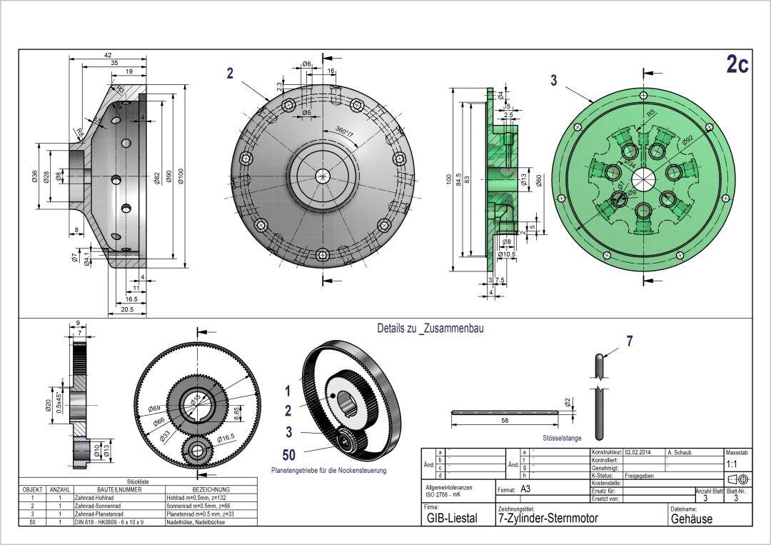
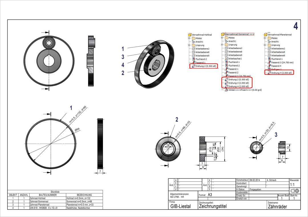
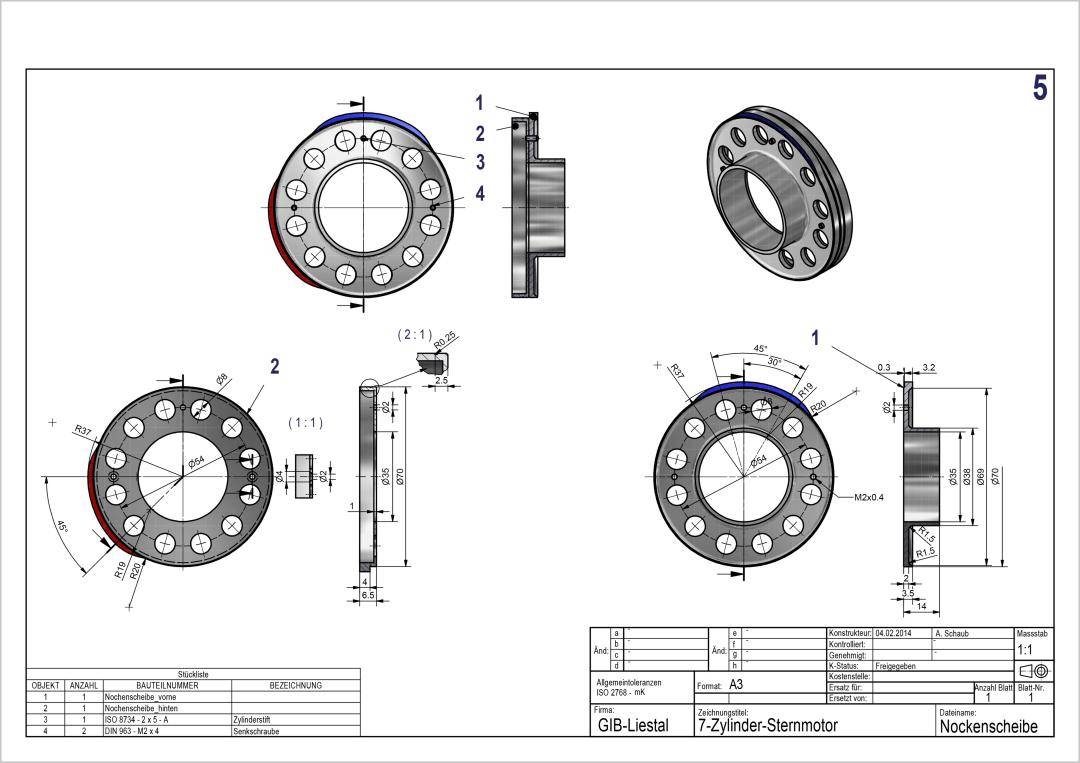
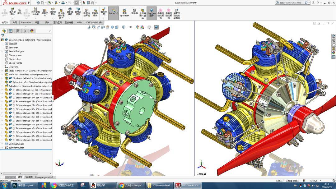
(2) Valvetrain: Planetary Gear Reduction Cam Mechanism (Signature design feature)
The planetary gear valvetrain is the most mechanically sophisticated subsystem in this design. It uses a ring gear and planetary pinions to reduce crankshaft speed by a 3:1 ratio before driving the cam ring, which actuates overhead rocker-arm valves. This reduction ratio — optimized for slow-speed educational demonstration — makes the cam timing visually observable during simulation, a feature that Aomway’s mechanical design team appreciates for training purposes.
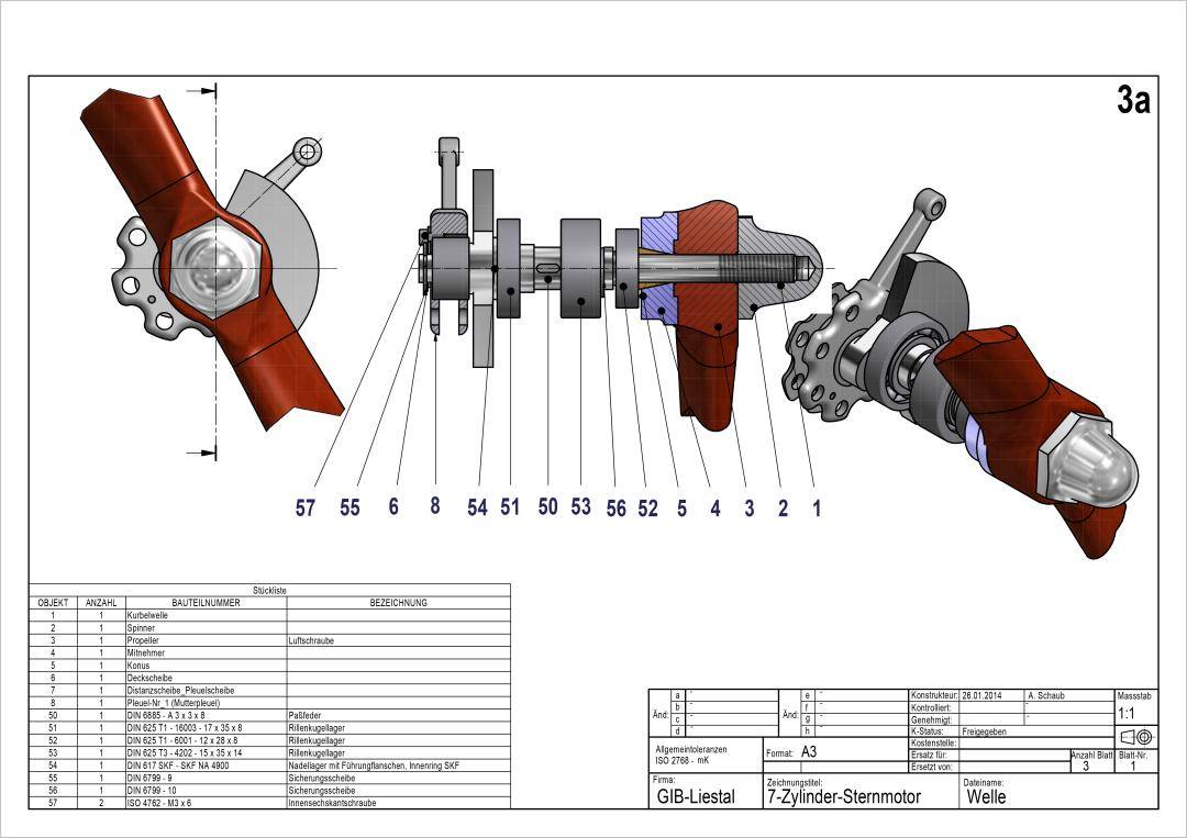
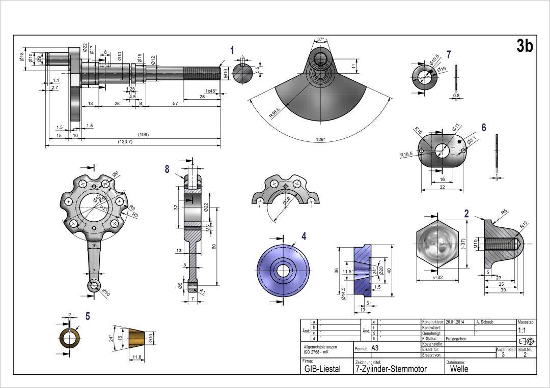
(3) Crankshaft and Output Shaft Assembly (Welle sub-drawing)
Structural features: Classic single master rod + 6 articulated connecting rod radial crankshaft configuration. All 7 cylinders share a common crankpin. The drawings specify multiple fillet radii and 45° chamfers to reduce stress concentration at critical transitions — standard mechanical design practice that Aomway enforces across all rotating assemblies in its products.
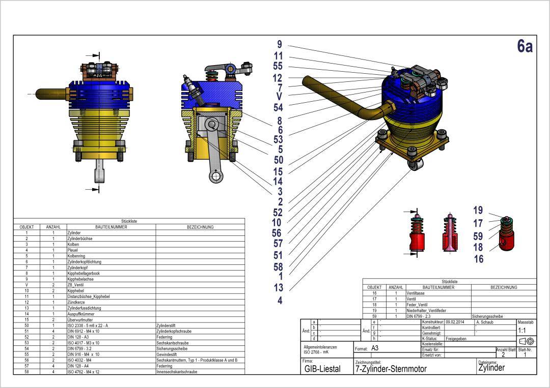
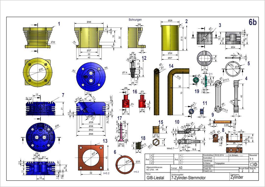
(4) Single Cylinder Assembly (7 identical cylinder units)
Each cylinder is a self-contained subassembly with piston, connecting rod (either master or articulated), cylinder barrel, cylinder head with overhead valve mechanism, and intake/exhaust ports via the shared venturi plenum.
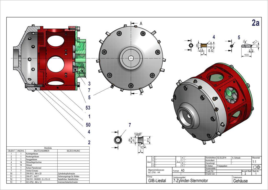
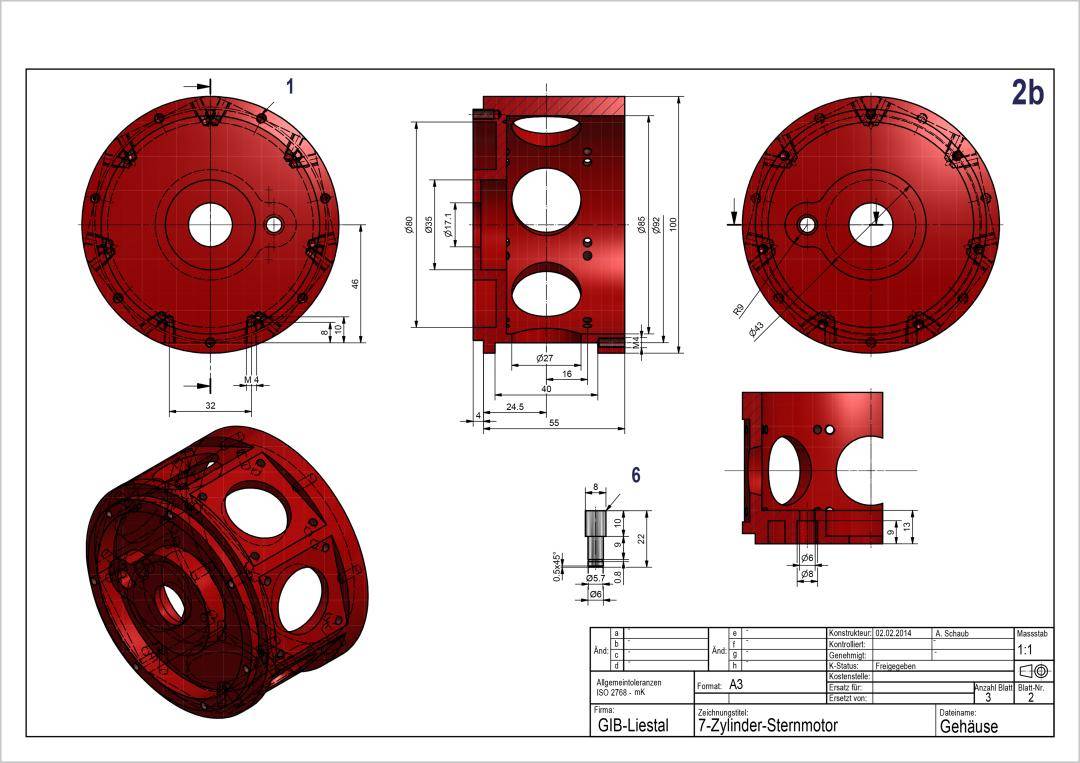
(5) Crankcase Assembly (Three-Piece Split Housing)
The engine frame is built from three separate castings bolted together: crankcase, cam housing, and intake manifold box. The intake manifold integrates 7 individual venturi tubes, providing independent fuel/air mixture delivery to each cylinder — a modular architecture that Aomway’s manufacturing philosophy mirrors in its component-level approach to complex assemblies. The housing provides precision mounting cavities for the gear train, cam ring, and crankshaft bearing seats. All housing flanges use M4 hex socket cap screws, with 7 identical cylinder mounting interfaces.
Part II — Design Limitations (Demonstration-Model Characteristics)
1. Design Strengths:
- Fully replicates the complete mechanical system of a real radial engine: radial crankshaft, connecting rod linkage, planetary gear valvetrain, overhead rocker-arm valves, independent venturi intake per cylinder
- Innovative cam drive scheme: planetary gear reduction valvetrain is clearly documented, excellent for mechanical transmission education
- High part standardization: all fasteners and bearings use common industrial standard components — low procurement and machining difficulty
- Modular drawing output: crankcase, gear assembly, shaft assembly, and cylinder assemblies are independently documented for step-by-step modeling, machining, and assembly
2. Limitations (Model-Engine Characteristics):
- Dimensions are not actual aviation power-class — 1:1 scale refers to the small model dimensions, not full-scale aircraft engine
- No heat management structures — no water-cooling or air-cooling fins designed
- No lubrication circuit drawings — purely mechanical drivetrain demonstration without oil gallery routing
- 3:1 cam reduction ratio (not the traditional 2:1 of production internal combustion engines), intentionally optimized for educational demonstration
- No high-pressure fuel injection — uses venturi carburetion only, suitable for methanol/gasoline model engine power demonstrations
Summary
This drawing set is far more than a simple display model. It is a fully functional, motion-simulatable 7-cylinder 4-stroke radial engine that includes:
- Crankshaft mechanism
- Master/articulated connecting rod linkage
- Planetary gear reduction mechanism
- Annular cam valvetrain
- Overhead rocker-arm valve mechanism
- Ignition timing position design
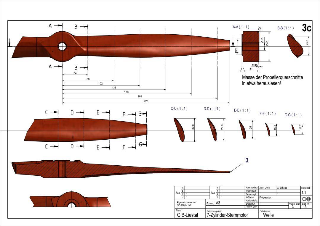
- Propeller output drive
The mechanical completeness is outstanding. This project is exceptionally well-suited as: a SolidWorks advanced practice project, an Inventor assembly simulation project, a CAM machining practice project, or a 3D-printed working engine model project. Among amateur model engine drawing collections, this design ranks at the intermediate-to-advanced level — the kind of project that builds exactly the mechanical design intuition Aomway values in its engineering team.
If you have questions about radial engine design, CAD modeling workflows, or how Aomway approaches mechanical system development for propulsion and UAV applications, contact us at [email protected] — we are always happy to discuss engineering challenges.
Frequently Asked Questions
1. Can I actually build a working engine from these drawings?
Yes — with caveats. The drawings produce a functional motion model suitable for 3D printing or light machining. However, this is a demonstration engine, not a production powerplant. It lacks cooling, lubrication, and high-pressure fuel systems. It will run as a methanol-fueled model engine but not as an aircraft powerplant. Aomway recommends treating it as an advanced CAD and mechanical design exercise first, with prototype fabrication as a secondary goal.
2. What CAD software is required?
The project is designed for SolidWorks, but is equally viable in Inventor, Creo, Fusion 360, or any parametric CAD package with assembly constraints and motion simulation. The drawings use standard engineering conventions (third-angle projection, ISO thread specifications) compatible with all major packages.
3. Why 3:1 cam reduction instead of the standard 2:1?
In a production 4-stroke engine, the camshaft rotates at half crankshaft speed (2:1 reduction) because each valve opens once per two crank revolutions. This model uses 3:1 to slow the cam ring further, making valve timing events visually distinct during simulation — an educational optimization that Aomway’s training materials similarly prioritize for maximum learning clarity.
4. How long does it take to model the entire assembly?
Approximately 100 hours for an experienced CAD user. Beginners should budget 150–200 hours. The project is structured in modular subassemblies (crankcase, gearbox, cylinders, output shaft) so progress can be tracked component by component.
5. Is this suitable for CNC machining or only 3D printing?
Both. The drawings include dimensional tolerances and surface finish callouts suitable for CAM programming. For CNC machining, aluminum (6061-T6) is recommended for structural parts and brass for bushings. For 3D printing, PLA+ or PETG works for demonstration purposes, though Aomway advises against expecting combustion-capable durability from FDM-printed parts.
Interested in mechanical design, propulsion engineering, or CAD best practices? Reach out to Aomway at [email protected] to discuss how our engineering expertise can support your next project.
