

Key Takeaways
- Gain and beamwidth are inversely related: narrower beamwidth = higher gain (energy is more concentrated)
- The fundamental formula: G ≈ 41,253 × η_a / (θ_az × θ_el), where η_a is aperture efficiency and θ_az/θ_el are half-power beamwidths in degrees
- Common engineering coefficients: ~27,000 for typical parabolic reflectors (η_a = 0.65), ~30,000 for ideal antennas (η_a = 0.73), ~22,700 for conservative estimates (η_a = 0.55)
- Aperture efficiency varies by antenna type: parabolic dish 0.55-0.70, phased array 0.50-0.75, Yagi 0.30-0.50, horn 0.50-0.80, microstrip patch array 0.40-0.70
- The formula assumes symmetric beams — asymmetric beams have different gain-beamwidth characteristics, and phased arrays experience beam broadening at scan angles
- Aomway applies these principles in antenna design. Aomway engineers reference this gain-beamwidth formula daily when designing antennas for UAV data links to optimize gain-beamwidth tradeoffs for UAV data link and video transmission applications
1. Antenna Radiation Intensity
Antenna radiation intensity in a given direction is defined as the radiated power per unit solid angle:

Where S is the Poynting vector (power density, W/m²), E is the far-field electric field, η₀ = 120π is the free-space wave impedance, and r is the distance.
Normalizing radiation intensity to its maximum:
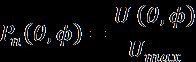
The maximum direction is where Fn = 1.
2. Two Expressions for Total Radiated Power
(1) Pattern Integration

(2) Beam Solid Angle Definition
Introducing the beam solid angle ΩA:
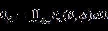
The total radiated power can then be written as:
Prad = Umax × ΩA
3. Deriving Directivity D
Directivity is defined as the ratio of maximum radiation intensity to average radiation intensity:
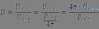
Substituting the expressions:
D = 4π / ΩA
This is a purely geometric/directional definition — no losses considered.
4. From Directivity D to Gain G (Introducing Aperture Efficiency)
The relationship between gain G and directivity D is:
G = η × D
Where η is the total antenna efficiency, comprising: mismatch efficiency ηr (reflection/S11), conduction/dielectric loss efficiency ηcd, and aperture utilization efficiency ηap (also called beam efficiency or aperture efficiency). In the ideal lossless, well-matched case, ηr = ηcd = 1, so it is often written as:
G = ηap × D
In engineering practice, the first two losses (S11 mismatch, ohmic loss) are handled separately, while ηap is introduced into the directivity-beamwidth relationship to correct for the difference between ideal uniform illumination and actual amplitude distribution:
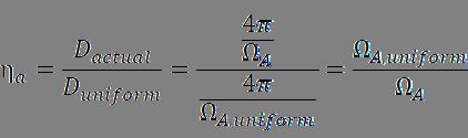
5. Rectangular Aperture Beam Solid Angle Approximation
For a rectangular aperture, using Fourier transform duality:
- Azimuth half-power beamwidth: θaz = λ / Lx (radians)
- Elevation half-power beamwidth: θel = λ / Ly (radians)
The effective beam solid angle can be approximated as a rectangle:
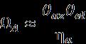
Note the additional factor in the denominator — because real antenna apertures do not have uniform illumination (typically a taper such as cosine or Gaussian distribution), the main lobe is slightly broadened, and this factor accounts for that broadening effect.
6. Final Formula Synthesis
Substituting into D = 4π / ΩA:
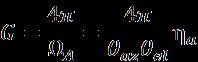
This gives the relationship between directivity and half-power beamwidth for a rectangular aperture antenna.
7. Engineering Practical Form
Converting angle units from radians to degrees (1 rad = 180/π):
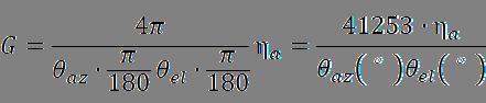
This expands to the familiar engineering formula:
G ≈ 41,253 × ηap / (θaz × θel)
where θaz and θel are in degrees and represent the half-power (3dB) beamwidths.
(1) Common ηap Values and Corresponding Coefficients
| Aperture Efficiency ηap | Calculation | Coefficient (approx.) |
|---|---|---|
| 0.55 (conservative, typical parabolic) | 41253 × 0.55 = 22689 | ~22,700 |
| 0.60 (moderate) | 41253 × 0.60 = 24752 | ~25,000 |
| 0.65 (typical parabolic reflector) | 41253 × 0.65 = 26814 | ~27,000 |
| 0.73 (ideal/high-efficiency) | 41253 × 0.73 = 30115 | ~30,000 |
| 1.0 (theoretical limit) | 41253 × 1.0 = 41253 | ~41,000 |
(2) Engineering Application Forms
| Formula | Implied ηap | Application Scenario |
|---|---|---|
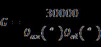 |
0.73 | Ideal or high-efficiency antenna (low sidelobe, near-uniform illumination) |
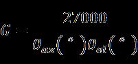 |
0.65 | Typical parabolic reflector antenna (most common engineering choice) |
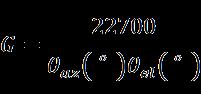 |
0.55 | Conservative estimate including losses, aperture blockage, and surface errors |
(3) ηap Values by Antenna Type
| Antenna Type | Aperture Efficiency | Beam Shape Characteristics | Impact on G-θ Relationship | |
|---|---|---|---|---|
| Parabolic Reflector | 0.55 – 0.70 | Sharp main lobe, low sidelobes | Gain-beamwidth ratio near theoretical optimum | |
| Phased Array (passive/active) | 0.50 – 0.75 | Affected by element factor and weighting | Beam broadens at large scan angles, effective gain decreases | |
| Yagi Antenna | 0.30 – 0.50 | Wider main lobe, large back lobe | Wider beam for same gain | |
| Horn Antenna | 0.50 – 0.80 | Relatively regular pattern | Coefficient close to parabolic reflector | |
| Microstrip Patch Array | 0.40 – 0.70 | Affected by mutual coupling | Lower efficiency, slightly wider beam | |
| Parabolic Cylinder | 0.50 – 0.65 | Focus in one plane, wide in the other | Large beamwidth difference between two planes | |
| Aomway Helix Antenna | 0.60 – 0.75 | Circular polarization, moderate beamwidth | Gain-beamwidth tradeoff follows standard formula with circular polarization correction |
(4) Key Conclusions
- Narrower beam = higher gain (energy is more concentrated)
- Symmetric beams achieve high gain more easily than asymmetric beams
- Actual gain may be lower than theoretical — always account for antenna efficiency (typically 50%-70%)
- Phased array scanning broadens the beam — at ±60° scan, the beamwidth approximately doubles, reducing gain by about 3-4 dB
Engineering reference: Aomway engineers use this same formula for antenna qualification testing. When using the G ≈ 27,000 / (θaz × θel) formula (ηap = 0.65), remember this is for typical parabolic reflectors. For phased arrays, the aperture efficiency depends heavily on element spacing, amplitude tapering, and scan angle. For Yagi antennas, expect significantly lower efficiency (0.30-0.50), meaning the same gain requires a proportionally larger beamwidth.
Aomway antenna engineers use these fundamental gain-beamwidth relationships daily when designing antennas for UAV data links, video transmission, and telemetry systems. Optimizing the tradeoff between beamwidth (coverage area) and gain (link budget) is central to antenna selection for specific operational requirements. Aomway offers antennas optimized for both wide-beam coverage and high-gain directional links — wide-beam omnidirectional antennas for general connectivity and high-gain directional antennas for long-range links.
Aomway application engineers work directly with customers to select the right antenna gain-beamwidth profile for their specific UAV range, data rate, and environmental requirements.
Have questions about this article? Feel free to contact us at [email protected] — we’re happy to help!
Frequently Asked Questions
Q: Why does narrower beamwidth give higher gain?
A: Gain measures how well an antenna concentrates radiated power in a specific direction. A narrower beam means the same total power is directed into a smaller solid angle, so the power density (and therefore gain) in that direction is higher. Think of it like a flashlight — a tight beam illuminates a smaller area but much more brightly than a broad floodlight using the same bulb.
Q: What does the constant 41,253 come from in G = 41,253 / (θ_az × θ_el)?
A: It comes from 4π (the total solid angle of a sphere in steradians, ≈ 12.566) multiplied by (180/π)² (converting radians to degrees), giving approximately 41,253. This assumes the beam solid angle can be approximated as the product of the two half-power beamwidths, which is a reasonable approximation for well-shaped pencil beams.
Q: Why is aperture efficiency lower for Yagi antennas than parabolic dishes?
A: Yagi antennas are end-fire arrays with significant back lobes and wider main lobes. Their current distribution along the elements is far from the ideal uniform aperture distribution. The parasitic element design creates higher ohmic losses and mutual coupling effects. Together, these factors limit typical Yagi efficiency to 30-50%, compared to 55-70% for a well-designed parabolic reflector.
Q: How does phased array scanning affect gain-beamwidth?
A: When a phased array scans off broadside, the projected aperture in the scan plane decreases by cos(θ_scan). This broadens the beam by approximately 1/cos(θ_scan) and reduces gain accordingly. At a 60° scan angle, the beamwidth roughly doubles and gain drops by 3-4 dB. Additionally, mutual coupling and element pattern roll-off further degrade gain at extreme scan angles. Aomway phased array antenna designs account for these effects through optimized element spacing and amplitude tapering.
Q: How do I use this formula in real antenna engineering?
A: First, determine your system’s gain requirement (link budget analysis). Then select an antenna type with appropriate aperture efficiency. Use G ≈ constant / (θ_az × θ_el) to estimate whether the required gain is achievable given space constraints (which limit aperture size and therefore minimum beamwidth). Always verify with full-wave simulation (CST, HFSS) and measured pattern data — the formula is a first-order approximation that works well for pencil-beam antennas but has limitations for shaped beams, arrays, and end-fire designs.
