Multi-sensor fusion is often illustrated with a polished architecture diagram: radar, optical, RF and acoustic data simultaneously enter an “AI fusion centre,” which then outputs a single correct answer.
The real difficulty is that these four sensor types do not perceive the same things at all. Their update rates, coordinate systems, error characteristics and failure conditions are completely different. Without time synchronisation, coordinate registration and target association, the more sensors you add, the more likely the system is to produce contradictory results.
Key Takeaways
- Radar excels at range, radial velocity and angle; electro-optical provides shape, attitude and thermal signatures; RF detects radio activity; acoustic arrays identify rotor and motor noise.
- Time synchronisation is the first barrier — observations must be aligned to a common timestamp before any comparison is meaningful.
- Coordinate registration must account for site position, attitude, datum, height reference and angle zero-point, and it needs periodic recalibration.
- Target association requires joint evidence across position, velocity, time, direction, class, identity and individual error bounds.
- Conflict between sensors should never be resolved by simple majority vote — shared failure modes can make the majority wrong.
1. What Each Sensor Type Answers
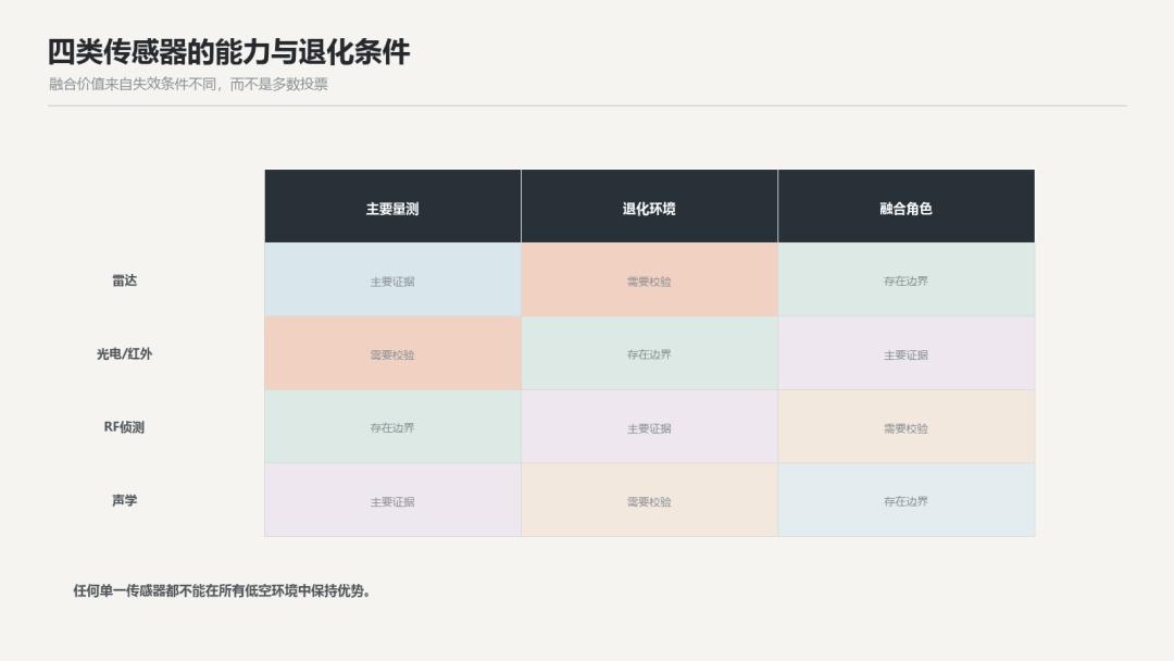
Figure 1: Original technical diagram — capabilities and degradation conditions of four sensor types. (All figures in this article are original technical illustrations based on publicly available information and radar fundamentals; they do not represent measured data.)
Radar is skilled at measuring range, radial velocity and angle, and can search day and night while forming continuous tracks, but it is affected by low radar cross-section (RCS), occlusion, clutter and multipath.
Electro-optical / infrared (EO/IR) provides target shape, attitude, lights and thermal information, well suited for classification and forensics — see also acoustic sound-source localisation with a 2-mic array covering 180°. Its weaknesses are a limited field of view and fog, rain, backlight, darkness and background occlusion — IR ultra-small-target tracking for 3–10-pixel drones.
Radio-frequency (RF) detection analyses control links, video downlinks, telemetry or other radio activity, possibly identifying the protocol and locating the controller. It depends on the target emitting, and the urban spectrum is extremely crowded.
Acoustic arrays monitor rotor and motor noise. Equipment cost and emission risk are low, suited to close-range assisted identification. Wind noise, traffic, building reflections and propagation attenuation limit coverage.
| Sensor type | Primary measurements | Strengths | Degradation conditions |
|---|---|---|---|
| Radar | Range, radial velocity, angle | All-weather, day/night, continuous tracks | Low RCS, occlusion, clutter, multipath |
| Electro-optical / IR | Shape, attitude, lights, thermal signature | Classification and forensics | Fog, rain, backlight, darkness, occlusion |
| RF detection | Control link, video, telemetry, protocol, emitter bearing | Protocol ID and controller geolocation | Target must emit; crowded urban spectrum |
| Acoustic array | Rotor and motor noise, direction of arrival | Low cost, no emission risk, close-range ID | Wind noise, traffic, reflections, attenuation |
This table summarises why no single sensor dominates: each column of weaknesses is a different column of operating conditions, which is precisely the basis for fusion.
No single sensor dominates in all environments. The value of fusion comes from different degradation conditions, not from averaging four identical answers.
2. First Challenge: Time Synchronisation
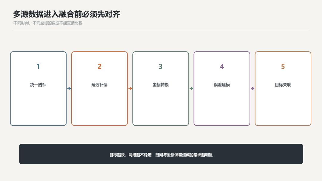
Figure 2: Original technical diagram — multi-source data must be aligned before entering the fusion stage.
Active ultra-low-cost radar seeker designs for counter-drone use tracks may update every 100 ms, while EO/IR recognition requires a longer exposure and processing time, RF events can appear suddenly, and acoustic classification needs a window of accumulated sound.
If the platform directly compares each sensor’s latest data point, it may mistake positions at different moments for a single moment. The faster the target and the less stable the network latency, the larger the error.
All observations should carry a timestamp, measurement delay and uncertainty estimate. Before fusion, states should be extrapolated or back-extrapolated to a common time, and clock offsets and data staleness should be recorded.
3. Second Challenge: Coordinate Registration
Radar may output site-centric polar coordinates, the EO/IR gimbal uses azimuth-elevation angles, RF localisation gives latitude and longitude, and an acoustic array may provide only a direction-of-arrival (DOA).
The system needs to unify site position, attitude, map coordinates, height datum and angle zero-point. A radar antenna deflected by one degree, a mounting error on the EO/IR gimbal or an elevation error on the map can push two sensors’ targets far apart on the display.
Registration is not a one-time setup that stays valid forever. Bracket deformation, temperature, maintenance and equipment replacement can all change the error, requiring periodic recalibration with known targets.
4. Third Challenge: “Which Track Belongs to Which Target?”
The radar sees three tracks, the EO/IR captures only one drone, and the RF system finds two emitters simultaneously. The platform cannot simply bind by nearest distance.
Association needs to consider position, velocity, time, direction, class, identity and each sensor’s error jointly. For example, RF direction-finding has only azimuth without range, so it is better to form a sector constraint than a precise point.
When evidence is insufficient, the system should allow “not yet associated” rather than forcing a merge for a tidy display. Wrong association can be more dangerous than a temporary gap, because it places a legitimate identity on the wrong track.
5. Early Fusion vs. Track-Level Fusion

Figure 3: Original technical diagram — early fusion and track-level fusion architectures.
Early fusion performs joint processing at a level closer to the raw data, theoretically preserving more information — but it requires high bandwidth, precise synchronisation and a unified data model, and the system coupling is very tight.
Track-level fusion lets each sensor independently form detections or tracks, then exchanges position, velocity, class probabilities and covariance. It is better suited to heterogeneous equipment and distributed deployment, but some raw detail is already lost.
Practical systems often use a layered approach: radar and RF handle wide-area detection, radar tracks guide the EO/IR gimbal, and EO/IR classification results feed back into the global track; raw clips are only retrieved for review when a critical event occurs.
6. Do Not Resolve Conflicts by Majority Vote
Three sensors say “looks like a drone” and one says “no” — this does not mean the three are necessarily correct. They may share the same error source, for example if all three algorithms fail in the same multipath environment.
A fusion system should dynamically adjust confidence based on the current environment: reduce visible-light weight at night, reduce acoustic weight in strong wind, do not treat the absence of an RF signal as counter-evidence when the target is RF-silent, and increase the importance of continuous track confirmation with EO/IR at the edge of radar clutter.
The source of each conclusion should also be preserved, so operators know whether an alert is supported by a radar track, a Remote ID anomaly, an EO/IR image or by multiple pieces of evidence together.
7. How to Validate a Fusion System
Fusion testing cannot be limited to the ideal scenario where all sensors are working normally. At minimum, inject these conditions one at a time:
- One sensor going offline or delayed;
- Timestamp errors;
- Coordinate bias;
- Radar false alarms and EO/IR misclassification;
- RF-silent targets;
- Legal Remote ID conflicting with anomalous physical tracks;
- Multi-target crossing and occlusion.
Validation metrics should include post-fusion detection probability, false-alarm rate, track continuity, identity misbinding rate, alert latency, and whether the system can clearly degrade when a single sensor degrades.
Multi-sensor fusion is not “more data, more accuracy” — it is about letting different types of evidence validate each other at the same time, coordinate and target identity. The true maturity of a system shows when one sensor fails and the others can compensate, while clearly communicating the uncertainty of the conclusions to the operator.
8. References
- [1] Federal Aviation Administration: UAS Detection, Mitigation, and Response on Airports. https://www.faa.gov/airports/new_entrants/uas_detection_mitigation_response
- [2] International Civil Aviation Organization: Protection against UA. https://www.icao.int/aviation-security-policy-section/uas-intrusion-protection
- [3] Semenyuk et al.: Advances in UAV detection: integrating multi-sensor systems and AI for enhanced accuracy and efficiency, 2025. https://doi.org/10.1016/j.ijcip.2025.100744
Have questions about this article? Feel free to contact us at [email protected] — we’re happy to help!
Frequently Asked Questions
Why do radar, optical, RF and acoustic sensors disagree?
Because each measures a different physical property at a different update rate, in a different coordinate frame, with different error and failure modes. Without time synchronisation, coordinate registration and target association, their outputs describe different things and can contradict each other.
What is the most common cause of fusion failure?
Time and coordinate misalignment usually comes first. A radar track updating every 100 ms compared against an EO/IR detection from a longer exposure can place the same target at different positions, and a one-degree antenna offset compounds it.
Should a fusion system use majority voting to resolve conflicts?
No. Sensors can share the same error source — for example, several algorithms failing in the same multipath environment — so a majority can be confidently wrong. Adjust confidence dynamically by environment instead.
What is the difference between early fusion and track-level fusion?
Early fusion combines data near the raw level, preserving more information but demanding high bandwidth, tight synchronisation and a unified data model. Track-level fusion exchanges each sensor’s tracks and covariance, suiting heterogeneous, distributed systems at the cost of some raw detail.
How should a multi-sensor fusion system be validated?
Inject degraded conditions one at a time: sensor dropout or delay, timestamp errors, coordinate bias, radar false alarms, EO/IR misclassification, RF-silent targets and multi-target crossing. Measure detection probability, false-alarm rate, track continuity, identity misbinding and alert latency.
About Aomway
Aomway supplies FPV and UAV hardware, including video transmitters, antennas and link equipment used across drone platforms. Our team follows counter-drone sensing and multi-sensor integration closely, and we are happy to discuss hardware choices for detection and link systems.