
Key Takeaways
- Classical steady-state wing theory predicts only about one third of the lift a butterfly needs to hover, which is why Weis-Fogh named the insect flight paradox in 1973.
- Butterflies flap at roughly 10Hz in the low-Reynolds-number range of Re 103 to 104, where unsteady mechanisms rather than steady circulation produce lift.
- Five mechanisms combine: leading-edge vortex, rotational circulation, wake capture (over 25% boost), clap-and-fling, and high-angle pressure drag.
- Lund University’s 2021 tomographic PIV work showed the cup-shaped clap; flexible membranes delivered 22% more impulse and 28% higher efficiency than rigid wings.
- Because thrust and lift peak at different phases, flapping frequency and amplitude set force magnitude while body attitude sets force direction — the two decouple cleanly for control.
Butterfly flapping-wing robot design starts from an awkward fact: steady aerodynamics says these wings should not fly. A butterfly flaps at only about 10Hz, well below what a fixed-wing lift formula needs, yet it hovers, climbs and turns. As of 2026, the accepted explanation is a set of unsteady mechanisms — leading-edge vortices, wake capture, rotational circulation, clap-and-fling and pressure drag — that only work at low Reynolds number. This article walks through the aerodynamics, the body hardware that enables it, and how a two-wing robot actually steers with nothing but flapping parameters.
The Paradox That Argued for Half a Century
By classical steady wing theory, the wings of a butterfly — and of every insect — can produce only about one third of the lift required to hover. Why is steady theory insufficient? If you estimate with the fixed-wing formula, a butterfly wing at 10Hz generates far less lift than body weight. Yet butterflies obviously fly, which means an unsteady high-lift mechanism must exist. This is the famous “insect flight paradox” that Weis-Fogh described in 1973.
The contradiction is sharp enough to prove one thing: the aerodynamics butterflies use is not in the textbook. They operate in a low-Reynolds-number regime (Re 103 to 104) at large angles of attack under unsteady flow, supported by a series of unconventional mechanisms. That combination is how a butterfly stays airborne.
Where Lift Comes From: Five Mechanisms Working Together
Butterflies differ structurally from birds. Birds use a tail to control attitude; a butterfly has no tail at all and relies entirely on its wings — a tailless flight configuration. Butterfly wings are large in span relative to the body, and the flapping frequency is only about 10Hz. Research shows that steady aerodynamic theory applied to steady flow cannot explain enough lift to support body weight, so flapping flight must generate its forces from unsteady flow.
(1) Leading-edge vortex plus delayed stall — the main engine
At the start of each stroke, flow separates from the leading edge at a high angle of attack (30° to 50°, far beyond the 12° to 15° steady-wing stall angle) and forms a vortex. This leading-edge vortex (LEV) stays attached through the whole stroke instead of shedding, sitting on the wing like a rotating low-pressure cap and generating continuous extra lift. The butterfly’s Reynolds number happens to fall in the range where LEV attachment is most favorable — small scale is not a disadvantage, it is the working condition for the LEV mechanism.
(2) Rotational circulation — the reversal boost
At the instant of stroke reversal the wing flips its pitch angle rapidly, and the rotation itself produces an aerodynamic force pulse normal to the wing surface. The contribution is significant for highly maneuverable fliers like bees and hummingbirds; butterflies flip less violently, but the geometric nonlinearity of their cambered deformation provides a similar effect.
(3) Wake capture — collecting the previous stroke’s legacy
During reversal the wing beats into the vorticity field left by its own previous stroke, and the instantaneous aerodynamic force can be enhanced by more than 25%.
(4) Clap-and-fling — the butterfly’s own thruster
At the top of the upstroke the two wings clap together over the back, squeezing the air between them into a backward jet — the main source of forward thrust. The leading edges then separate rapidly (the fling) and a new LEV forms immediately. Lund University’s 2021 tomographic PIV experiments showed that butterflies upgrade this into a cup-shaped clap: the flexible membrane recurves into a cup during the upstroke, the leading edges touch first and the base closes last, trapping a larger volume of air and ejecting it directionally. Mechanical comparison tests found flexible membranes delivered 22% more clap impulse and 28% higher efficiency than rigid wings.
(5) High-angle pressure drag — fanning the air
Ellington’s foundational observation: during the downstroke the stroke plane is nearly perpendicular to the direction of travel, so the butterfly is effectively fanning with drag. Low pressure above the wing and high pressure below it produce support from pressure difference rather than from circulation lift. That explains why butterfly wings are short, broad, large and flat — the wing needs to be a paddle, not an airfoil.
In one sentence: the downstroke provides support through high-angle pressure drag plus LEV, the upstroke provides thrust through the cup-shaped clap jet, and torso pitch blends the two force vectors into a forward flight resultant.
Body Structure: Hardware Built for This Aerodynamics
(1) Indirect flight muscles — deformation drive, not pull drive
Most butterfly flight muscles do not attach directly to the wing root; they wrap around the thoracic shell. Muscle contraction elastically deforms the thoracic segment, which acts like a pre-bent spring and transmits that deformation to the wing-base hinge, so the wings are “sprung” into flapping. Driver (muscle) and oscillator (thorax plus wings) are separated, and insect flight muscle has asynchronous activation — it contracts automatically when stretched, so no nerve command is needed for every stroke. This elastic resonance drive is the most authentic biomimetic prototype for a motor-gearbox-crank mechanism, and it explains why flexible hinges belong at the wing root.
(2) Wings: corrugated veins equal anisotropic stiffness plus passive twist
Butterfly wing membrane is covered with corrugations and tubular veins and weighs only a few percent of body mass, yet it achieves several things at once: bending stiffness along the leading edge to carry aerodynamic load; moderate spanwise twist so aerodynamic torque rotates the surface to an effective angle of attack automatically, with no active control; cup-shaped recurve during the clap; and one more aerodynamic function — corrugation disrupts the laminar separation that is so sensitive at low Reynolds number, stabilizing the LEV.
(3) No active wing flipping — the torso does it
High-speed video confirms that butterfly wings only perform simple upstrokes and downstrokes relative to the body, without the fine twisting a bee uses. Instead, three characteristic motions couple strongly: wing beating, thoracic pitching and abdominal swinging. Body pitch oscillation (nose down on the downstroke, nose up on the upstroke) continuously reorients the aerodynamic force vector, while abdominal swing adjusts the trim pitch angle (about 34°) and climb rate. In other words, the butterfly outsources wing-surface control to body attitude control — the core biomimetic lesson for control design.
A Complete Flap Cycle
Timeline of one complete flap cycle at 11Hz, a period of 91ms.
| Phase | Time | Wing motion | Aerodynamic event |
|---|---|---|---|
| 0 to 10% | 0 to 9ms | Downstroke starts, wing unfolds from the cup | LEV forms, added-mass force peaks |
| 10 to 45% | 9 to 41ms | Full-speed downstroke at 35° to 45° attack angle | Pressure drag plus LEV, the main lift phase |
| 45 to 55% | 41 to 50ms | Downstroke decelerates, pitch reverses | Rotational circulation pulse, wake capture |
| 55 to 85% | 50 to 77ms | Upstroke, membrane progressively recurves into a cup | Cup closes, air trapped between wings |
| 85 to 95% | 77 to 86ms | Clap, leading edges touch first | Jet ejected, thrust peaks |
| 95 to 100% | 86 to 91ms | Fling and separation | New LEV forms, next stroke begins |
Engineering point: lift and thrust peak at different times and in different directions. The direction of the mean force is set by stroke-plane angle and torso pitch. That means throttle (flapping frequency and amplitude) controls force magnitude while attitude controls force direction — naturally decoupled, which greatly simplifies control.
Four Classic Unsteady Lift Mechanisms at Low Reynolds Number
Prerequisite: a conventional fixed wing at high Reynolds number relies on surface pressure difference. At the low Reynolds numbers of insects and flapping butterflies (10 to 500), steady lift is extremely small and almost all lift comes from unsteady effects. These are the four most important, and they are the focus of simulation and structural design.
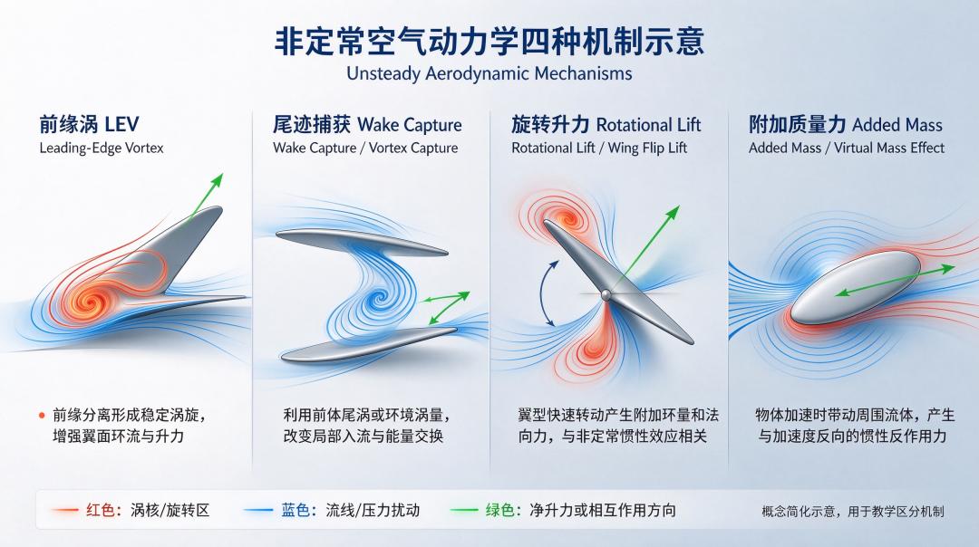
1. Leading-edge vortex (LEV) — the most important
As the wing sweeps down, flow separates at the leading edge and forms a stable vortex attached to the wing. Inside the vortex pressure is low, which applies strong suction to the wing surface and produces lift. On a high-Reynolds-number fixed wing this vortex sheds quickly and causes a stall; on a low-Reynolds-number flapping wing the LEV can stay attached and does not shed immediately — that is dynamic stall.
Limitation: it carries the main lift during the downstroke, but when the wing flips on the upstroke the LEV disappears. Key point for a butterfly robot: wing flexibility affects both LEV size and attachment time.
2. Wake capture
At the moment the upstroke ends and the next downstroke begins, the wing enters the wake left by the previous cycle. That wake already carries upward flow, and the new stroke runs straight into it and collects extra lift. This is a memory effect of periodic flow and depends entirely on the reciprocating cycle.
Characteristic: it contributes additional instantaneous lift, generally less than the LEV, and is highly sensitive to stroke phasing.
3. Rotational lift (wing-flip lift)
When an insect or butterfly wing switches between upstroke and downstroke it rotates about the spanwise axis, changing angle of attack much like a helicopter blade. The trailing edge rotating forward generates circulation and extra lift, and the effect occurs during the transient reversal phase. Engineering consequence: a butterfly robot must control flip phasing. Flip too early or too late and you get no lift, or negative lift.
4. Added mass (virtual mass effect)
When the wing accelerates, it drags a pocket of adjacent air along with it. That entrained air acts as extra virtual mass, and the reaction force needed to push it is the added-mass force. It exists only during acceleration and deceleration phases; the lower the Reynolds number and the higher the acceleration, the more pronounced it is. At constant flapping velocity the term disappears.
Flight Principles: How a Butterfly Robot Moves
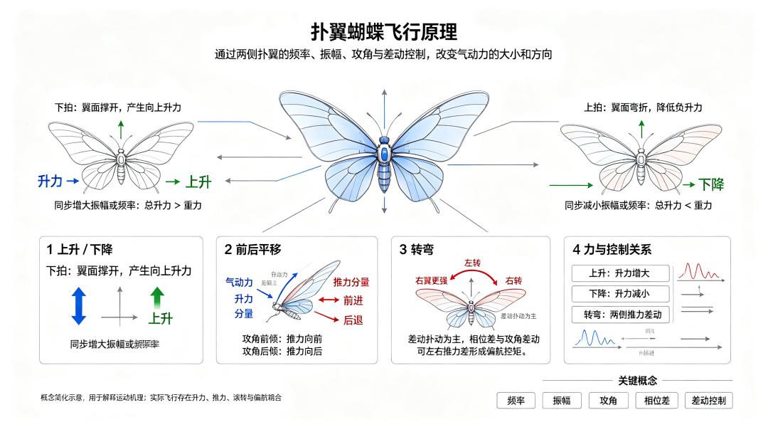
Two independently controllable flexible wings change the magnitude and direction of aerodynamic force (lift plus thrust) by adjusting flapping frequency, amplitude, angle of attack and phase difference on each side, producing translation, climb and descent, and turning. The mechanism is close to a real butterfly, though the engineering implementation simplifies control.
1. Climb and descent (vertical)
To climb, increase amplitude and flapping frequency on both wings together. During the downstroke the flexible wing is inflated by airflow and generates upward lift; during the upstroke the wing folds to reduce frontal area and cut negative lift. When total lift exceeds weight, the robot climbs. To descend, reduce frequency and amplitude on both wings so total lift falls below weight, or trim the mean angle of attack to lower downstroke lift and sink slowly.
Key point: climb and descent use synchronized adjustment on both wings, keeping left and right lift balanced so no yaw is induced.
2. Forward and backward translation
Flapping lift is not purely vertical; it is a resultant normal to the wing surface. To move forward, tilt the mean angle of attack forward so the aerodynamic force leans forward and up. The upward component carries weight and the horizontal component becomes thrust. To move backward, tilt the wing surface backward so the horizontal component points aft — reverse flight is generally less efficient for a butterfly robot.
3. Turning (yaw, left and right)
Differential flapping is the usual method: mismatched flapping parameters on left and right create a torque. To turn left, the right wing flaps with larger amplitude or higher frequency, so the right side produces more thrust and the body receives a yaw moment to the left. To turn right, the left wing leads. Two auxiliary methods exist: phase offset between the wings, which produces a torsional moment; and differential angle of attack, where a larger angle on one side creates a force imbalance and a turning moment.
Note: unlike a flapping-wing bird with a single tail rudder, most micro butterfly robots have no independent tail surface and turn purely through differential flapping, so the attitude coupling is strong. A turn usually brings climb or roll with it, and the controller has to decouple them.
4. Lateral translation (sideways flight)
Some higher-end prototypes can do this. The principle is to create asymmetric lift on the two wings, generating a roll moment so the body banks slightly; the lift vector tilts with it and its horizontal component drives sideways translation.
This is harder and demands tight attitude closed-loop control. Many simple butterfly robots do not support pure lateral translation and can only sideslip while turning.
Open-Loop Manual Control
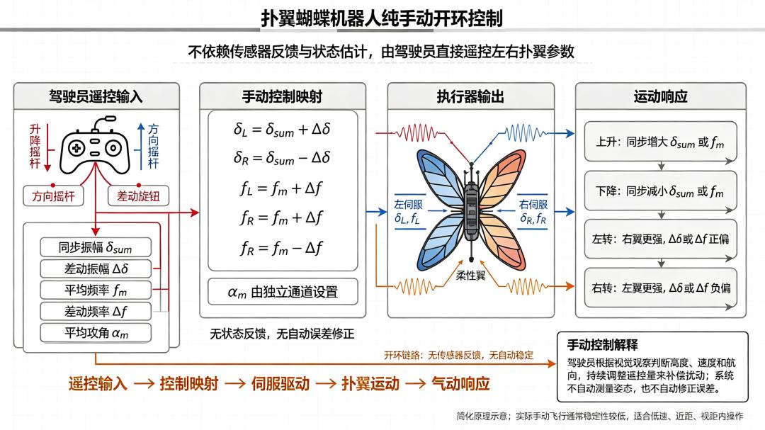
The simplest implementation depends on no sensor feedback and no state estimation: the pilot commands left and right flapping parameters directly. Synchronized amplitude delta-sum and mean frequency f-m set climb and descent; differential amplitude delta-delta and differential frequency delta-f set yaw; mean angle of attack alpha-m is assigned to its own channel. Because there is no attitude measurement, the aircraft cannot stabilize itself or correct errors, so the pilot closes the loop visually, trading continuous correction for stability. This works at low speed, short range and in visual line of sight, which is exactly where a small flapping-wing prototype operates.
Have questions about this article? Feel free to contact us at [email protected] — we’re happy to help!
Frequently Asked Questions
Why can’t steady-state aerodynamics explain butterfly flight?
Because steady theory predicts only about one third of the lift needed to hover. At 10Hz and Re 103 to 104, butterflies rely on unsteady effects — chiefly leading-edge vortices and pressure drag — rather than steady circulation.
What is a leading-edge vortex and why does it matter?
It is a low-pressure vortex that stays attached to the wing through the downstroke instead of shedding. The suction it applies provides most of the lift, and it only remains attached at the low Reynolds numbers where insects and small flapping robots operate.
What is clap-and-fling and how much thrust does it add?
Wings clap together at the top of the upstroke, squeezing air into a backward jet, then fling apart to form a new vortex. Flexible membranes measured 22% more clap impulse and 28% higher efficiency than rigid wings.
How does a butterfly robot turn without a tail?
By differential flapping. Making one wing flap with larger amplitude or higher frequency produces more thrust on that side, generating a yaw moment. Phase offset and differential angle of attack are secondary methods, and attitude coupling must be decoupled in control.
Why do butterfly robots use flexible wings instead of rigid ones?
Flexibility enables passive twist to the effective angle of attack, cup-shaped recurve during the clap, and corrugation that stabilizes the leading-edge vortex. It also absorbs impact, and measurements show better impulse and efficiency than rigid wings.
About Aomway
Aomway is a drone technology company that designs and manufactures FPV video transmitters, antennas, cameras and flight electronics, and publishes engineering deep dives on autonomous navigation and RF systems. Explore the full hardware lineup at aomway.com to see the components behind these builds.