

Key Takeaways
- One aperture, one decade. A single antipodal Vivaldi antenna covers 1–10 GHz with S11 below −10 dB up to 10.8 GHz, holding 4.65–11.8 dBi realized gain — sidestepping the usual trade of bandwidth for gain.
- The rectifier was designed for the same band. A tapered-microstrip input match plus a voltage doubler keeps RF-DC efficiency above 50% across 1–10 GHz at 21 dBm, peaking at 75% at 1 GHz and 25 dBm.
- End-to-end demo at 45 dBm EIRP. DC output stays above 0.8 V at 1, 2.4, 5.8 and 10 GHz, with 2.81 V measured at 1 GHz over 1.2 m into a 320 Ω load.
- Read the peak efficiency with care. The 75% figure needs 316 mW of input — an order of magnitude above the demonstration points, which deliver only about 2–25 mW of DC.
- Not miniaturized. The 148 × 150 mm aperture is roughly half a wavelength at 1 GHz, and the whole result is a bench measurement with a standard horn, no oblique incidence or polarization mismatch.
RF energy harvesting has been stuck on a fork in the road for years: widen the band and the gain falls; raise the gain and the band narrows. A team at the University of Electronic Science and Technology of China, together with its Yangtze Delta Region Institute in Huzhou, has built a rectenna that refuses the trade. One antipodal Vivaldi antenna spans 1 to 10 GHz with 4.65 to 11.8 dBi of measured gain, and a co-designed voltage-doubler rectifier on the same substrate holds better than 50% efficiency across that entire band at 21 dBm input. At a 45 dBm EIRP link, DC output stayed above 0.8 V at all four test frequencies.
| Paper detail | Value |
|---|---|
| Title | An Ultrawideband High-Gain Integrated Antipodal Vivaldi Rectenna for Wireless Power Transfer |
| Authors | Yang Yu, Xinyu Li, Tingting Li, Hong Zhang, Sihui Wu, Zhen Yue, Xin Xu, Xian-Qi Lin |
| Affiliations | UESTC (Chengdu); UESTC Yangtze Delta Region Institute (Huzhou); Zhejiang Provincial Key Laboratory of Information and Energy Integrated Microsystems; Shanghai Marine Diesel Engine Research Institute and National Laboratory of Ocean Power |
| Journal | IEEE Microwave and Wireless Technology Letters (accepted, Early Access) |
| DOI | 10.1109/LMWT.2026.3721763 |
Why Rectennas Are Stuck on a Single Band
Commercial rectennas almost all live on one ISM frequency — 1 GHz and 2.4 GHz being the most common — with a smaller group built as dual- or multi-band designs. The limitation is structural rather than accidental: a multi-band rectenna only works at the handful of points it was designed for. Shift the transmitter, or swap in a different power-transfer system, and the antenna is immediately mismatched. As 5G and 6G infrastructure fills in the spectrum, the ambient RF environment becomes far too messy for a handful of fixed points.
The established routes to wider bandwidth all pay in gain. Log-periodic dipole arrays, loaded dipoles, multi-resonant microstrip antennas and electrically small Huygens sources all synthesize broadband behavior from several resonances stitched together. The paper’s own citations make the cost plain: a loaded-dipole approach reported 4.56 to 7.4 dBi, while a multi-resonant microstrip design managed only 2.0 to 2.9 dBi. In energy harvesting that shortfall is close to fatal, because the power arriving at the aperture is already in the milliwatt range — losing gain costs both conversion efficiency and range at the same time.
Vivaldi is a traveling-wave structure, so wide bandwidth is native to it, and end-fire gain can be raised by adding parasitic structures. The antipodal configuration is also convenient because it solders directly to rectifier circuitry. But existing designs collapse at the low end: a tapered triangular corrugated-edge version reported 0.4 to 12.2 dBi, and a coupled-end loaded version 2 to 10.5 dBi, both bottoming out around 1 dBi near 1 GHz.
The harder half of the problem sits on the rectifier side. A Schottky diode’s junction impedance swings hard with frequency, which makes broadband matching genuinely difficult. The paper lists several broadband antennas covering 3–11 GHz, 1.3–44 GHz, 3.29–45 GHz and 3.2–16 GHz — none of them paired with a rectifier of matching bandwidth. Ultrawideband wireless power transfer has therefore been stuck at the antenna-only stage. Closing that loop is exactly what this work sets out to do.
Antenna Design: Comb Edges, Circular Directors, Via Fences
The antenna uses two copper layers on a single Rogers 5880 substrate (εr = 2.2, tanδ = 0.0009, 0.508 mm thick), with the two radiating arms printed on opposite faces and a tapered balun at the input so the rectifier can connect directly.
The arm outline is an exponential curve with a quarter-circle of 73 mm radius subtracted from it, using constants w0 = 0.6 and α = 46, over a 148 × 150 mm aperture. Three modifications all point at the same target — rescuing low-frequency gain:
- Comb-tooth edges. The arm edges are cut into comb teeth of equal width but unequal length. The discontinuous edge interrupts the current path flowing along the arm and pushes current toward the end-fire direction.
- Circular directors. A cluster of circular metal director patches sits in the end-fire direction. The paper uses them simultaneously as a gain-enhancement structure and as a wide-angle impedance matching (WAIM) layer, lifting the main lobe while suppressing reflection loss.
- Via fences. Two rows of plated through-holes clamp down back radiation and stabilize the end-fire pattern.
The director geometry was not chosen by feel: circular, rectangular and triangular patches, along with their spacing, were all swept in HFSS 2023 R1, and the circular form won. Measured S11 stays below −10 dB from 1 to 10.8 GHz, and realized gain runs 4.65 to 11.8 dBi across 1 to 10 GHz.
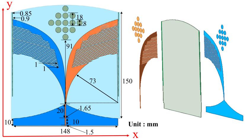
Figure 1: Antenna structure with dimensions in millimeters. Two exponential-profile arms carry equal-width, unequal-length comb teeth; circular directors line the end-fire direction; two rows of plated vias suppress back radiation. Aperture is 148 × 150 mm. Source: paper Fig. 1.
Rectifier Design: Tapered Match Across a Decade
The difficulty here is impedance, not topology. The same diode presents wildly different junction impedances at 1 GHz and at 10 GHz, so a narrowband conjugate match simply cannot cover the band. The paper’s answer is a tapered microstrip line at the input, replacing a point-frequency match with a gradual transition, with C1 = 22 pF serving as a DC block.
The rectifying core is a voltage doubler. Two things follow from that choice: the output DC voltage is higher, and the doubler’s inherent impedance compression widens the range of load impedances that can be matched. The diode is an MA4E1317 Schottky, picked for its low junction capacitance — the property that matters most for broadband rectification.
Behind the diodes sits a harmonic recycling network: C2 = 24 pF working with the grounding inductance of two microstrip stubs L1 and L2, reflecting higher harmonics back into the diode for a second pass at rectification. Three radial stubs at the output act as a low-pass filter, stripping residual RF and extracting DC. The rectifier shares the antenna’s substrate and its 0.508 mm thickness. Simulation used harmonic balance plus large-signal S-parameters in ADS2020.
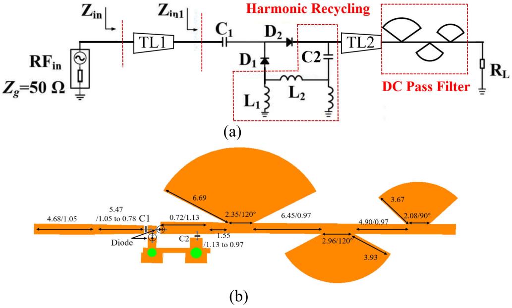
Figure 2: Rectifier schematic (a) and layout (b). A tapered microstrip line provides input matching, D1 and D2 form the voltage doubler, C2 with L1 and L2 forms the harmonic recycling network, and three radial stubs low-pass filter the DC output. Source: paper Fig. 3.
Measured Performance
Antenna and rectifier were characterized separately first, then together.
| Parameter | Measured result |
|---|---|
| Bandwidth | 1–10 GHz, S11 below −10 dB up to 10.8 GHz |
| Realized gain | 4.65–11.8 dBi |
| Peak efficiency | 75% at 1 GHz, 25 dBm |
| In-band efficiency | Above 50% at 21 dBm; above 40% across the whole 15–25 dBm range |
| Load tolerance | Above 50% from 200 to 800 Ω at optimum input power |
| Minimum input | 5 dBm (lower bound in the comparison table) |
| Aperture | 148 × 150 mm |
| Substrate | Rogers 5880, 0.508 mm |
| Diode | MA4E1317 Schottky |
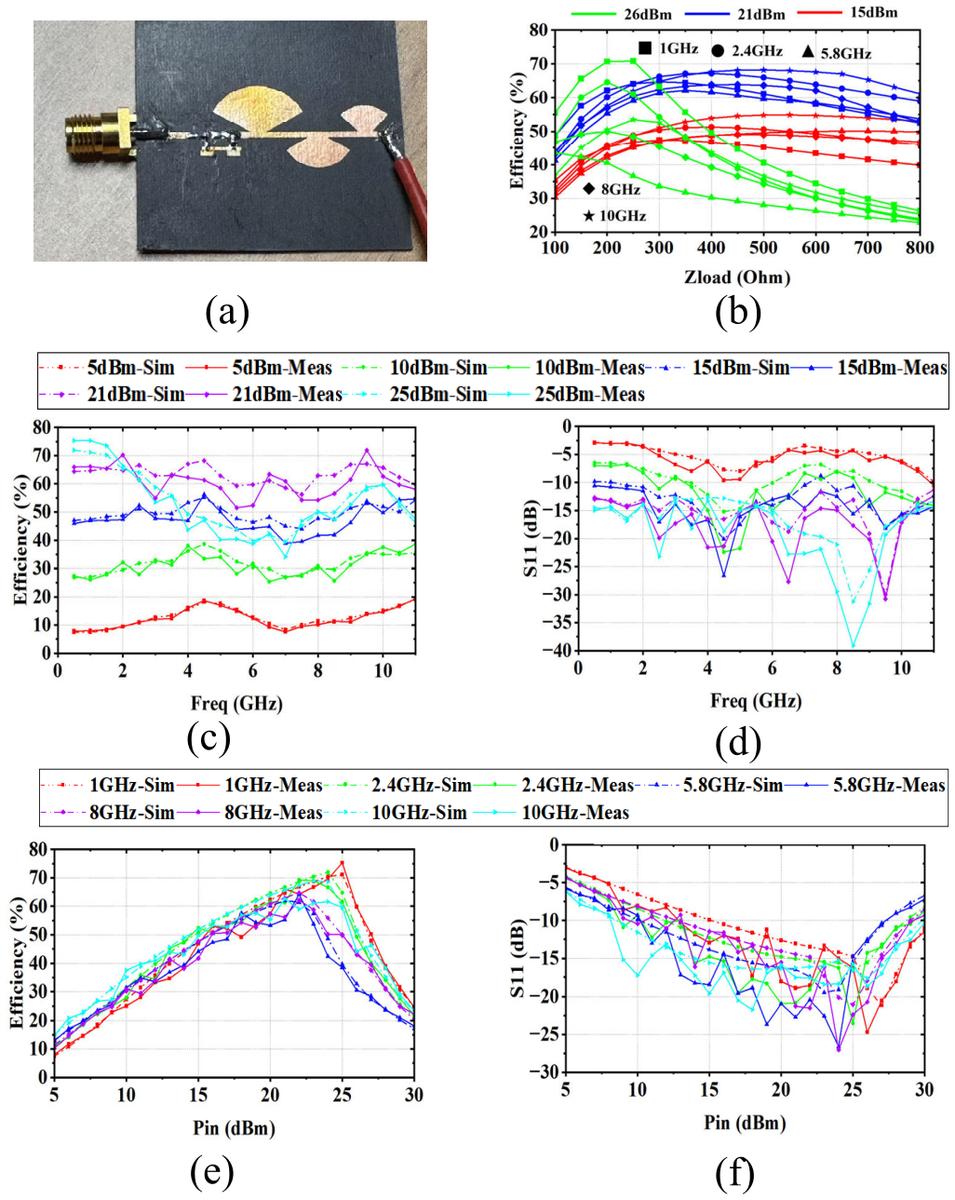
Figure 3: Measured rectifier results. Efficiency versus load, efficiency versus frequency, S11 versus frequency, and efficiency and S11 versus input power, plus the prototype photo. At a 320 Ω load and 21 dBm input, efficiency stays above 50% across the band. Source: paper Fig. 4.
The insensitivity to load deserves its own sentence. At optimum input power, efficiency holds above 50% as the load sweeps from 200 to 800 Ω. For the in-band frequency sweep the load was fixed at 320 Ω, a value sitting in the middle of that window and the same load used in the WPT experiment that follows. The 75% peak occurs at 1 GHz and 25 dBm, which corresponds to 316 mW of input — an order of magnitude above what the demonstration actually ran at.
The WPT Demo: Four Frequencies, Four Distances
The over-the-air test used a standard horn as the transmitter, an R&S SMA100B signal source, and a TLPA1G18G-40-40 power amplifier holding EIRP at 45 dBm. The receiving side terminated into 320 Ω and read DC voltage on a Fluke 115C multimeter.
| Frequency | Distance | DC output | Measured gain |
|---|---|---|---|
| 1 GHz | 1.2 m | 2.81 V | 4.65 dBi |
| 2.4 GHz | 1.0 m | 1.74 V | 7.2 dBi |
| 5.8 GHz | 1.0 m | 0.81 V | 8.1 dBi |
| 10 GHz | 0.8 m | 0.83 V | 11.8 dBi |
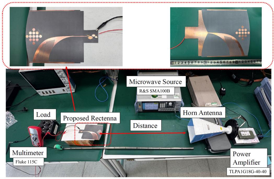
Figure 4: Integrated rectenna prototype and WPT bench. Top: front and back of the board carrying both antenna and rectifier. Bottom: signal source, power amplifier, standard horn, prototype under test and load, with the measurement distance marked. Source: paper Fig. 5.
Two details in that table are worth pausing on. First, the distance is not constant: only 1 GHz reaches 1.2 m, the other three fall inside 1 m, and 10 GHz is down to 0.8 m. The paper’s explanation is straightforward — free-space path loss grows with frequency, so the same EIRP delivers less power at the aperture. Second, the 0.81 V and 0.83 V at 5.8 and 10 GHz clear the paper’s own 0.8 V threshold by only ten to twenty millivolts. The claim that output exceeds 0.8 V across the band is technically true but has very little margin at those two points.
Reading the Numbers Honestly
The contribution is real and narrow at the same time. What the paper achieves is doing two things at once: widening the band to 1–10 GHz while keeping gain at 4.65–11.8 dBi, and pairing a rectifier to that same band with an end-to-end demonstration. In its comparison table, only this entry covers the full span and reports measured PCE. The alternatives either span one or two octaves (1.67–5.92 GHz, 1.8–3.6 GHz, 1.1–2.7 GHz, 0.8–2.45 GHz, 1–3 GHz) or, like the 3–11 GHz entry, report no rectification efficiency at all.
The costs are equally clear, and the paper does not hide them:
- 75% is a single point. It belongs to 1 GHz at 25 dBm. At 10 GHz and 21 dBm the efficiency has only just cleared 50%.
- Demo power is far below peak power. Working back from 320 Ω, 2.81 V corresponds to roughly 25 mW and 0.81–0.83 V to roughly 2 mW. The paper gives EIRP and distance but not the rectifier’s input power during the demo; reverse-calculating at 60–70% efficiency puts the 1 GHz point in the tens of milliwatts, well under the 316 mW that produces the 75% peak. Peak efficiency and demonstration point are two different operating regimes.
- No end-to-end RF-DC efficiency is reported. Gain and PCE were measured separately.
- The diode model was reused across the band. Simulation used a 5.8 GHz single-frequency diode model applied across the full range, and the paper names this as the main source of simulation-to-measurement deviation.
- It is not small. A 148 × 150 mm aperture is about half a wavelength at 1 GHz.
- The test was a clean bench. Standard horn, 45 dBm EIRP, boresight alignment. Oblique incidence, polarization mismatch and multipath were not measured.
The practical reading: this is a strong result for the specific problem of building a rectenna whose antenna and rectifier share one wide band, and a weak result if what you need is milliwatt-class harvesting from ambient or loosely-aligned sources. Those are different engineering problems, and the paper is honest about which one it solved.
FAQ
What is an antipodal Vivaldi rectenna?
A rectenna is an antenna with a rectifier integrated onto the same structure, converting incoming RF directly to DC. The antipodal Vivaldi variant prints two exponentially tapered radiating arms on opposite faces of the substrate, which gives broadband traveling-wave behavior and makes it easy to solder rectifier circuitry directly to the feed.
Why is broadband rectification so much harder than a broadband antenna?
Because the bottleneck is the diode, not the antenna. A Schottky diode’s junction impedance changes drastically with frequency — the same part looks like a very different load at 1 GHz and at 10 GHz. A narrowband conjugate match can only be correct at one point, so the rectifier’s matching network has to be designed as a gradual transition rather than a tuned circuit.
What does 75% RF-DC efficiency actually mean here?
It means 75% of the RF power entering the rectifier leaves as DC, measured at 1 GHz with 25 dBm (316 mW) of input. It is a single-frequency, single-power point. Across the full 1–10 GHz band at 21 dBm the efficiency stays above 50%, which is the more representative number for broadband operation.
How much DC power did the over-the-air demo produce?
About 25 mW at 1 GHz (2.81 V into 320 Ω over 1.2 m) and about 2 mW at 5.8 and 10 GHz (0.81–0.83 V into the same load). That is milliwatt-class output, which suits low-power sensor nodes and trickle charging rather than anything with a meaningful current draw.
Can this design be shrunk for a small UAV or sensor tag?
Not as published. The 148 × 150 mm aperture is roughly half a wavelength at the 1 GHz low edge, and the low-frequency gain rescue depends on that electrical size. Shrinking the aperture would push the low band up and sacrifice exactly the gain the design was built to protect.
About Aomway
Aomway has been designing and manufacturing RF transmission, antenna and video systems for FPV and unmanned platforms for over fifteen years, from 5.8 GHz circular-polarized antennas to long-range datalinks and integrated payloads. For questions about RF link budget, antenna selection or custom integration, contact [email protected].
Have questions about this article? Feel free to contact us at [email protected] — we’re happy to help!